38
9. Installation of tap-changer protection device and transmission
device components
9.1 Installation of gas relay
Install according to the instruction manual provided when the gas relay is supplied.
9.2 Use of pressure relief device
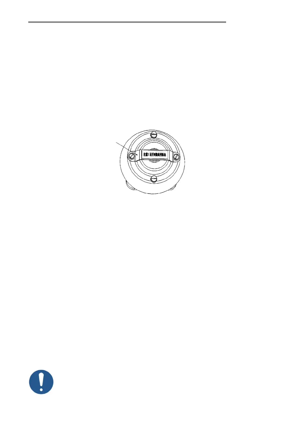
The red bar on the top of the pressure relief device must be removed before operation (Figure 9-1).
9.3 Installation of motor drive unit
The motor drive unit is used to drive the tap-changer to carry out the tap change operation; it
can be operated automatically or manually.
Attentions should be paid during the installation of motor drive unit:
6.3.1 The motor drive unit and tap-changer must be in the same setting position, which is
indicated in the tap-changer connection diagram supplied with the equipment.
6.3.2 The motor drive unit must be mounted at the provided place on the transformer tank in
a vertical position, deflection not allowed.
Attention: The mounting plate of the motor drive unit should be flat, otherwise the motor drive unit
will be deformed by twisting and its operation will be affected.
For the installation details of the motor drive unit, please see the operation instructions of SHM and CMA7
motor drive units.
9.4 Installation of bevel gear box
The bevel gear box is to be mounted onto the supporting bracket of the transformer tank by 2 bolts with
18mm bore diameter.
The serial number marked on the nameplate of the bevel gear box must be
consistent with the serial number on the nameplate of the tap-changer.
Figure 9-1 Pressure relief device