41
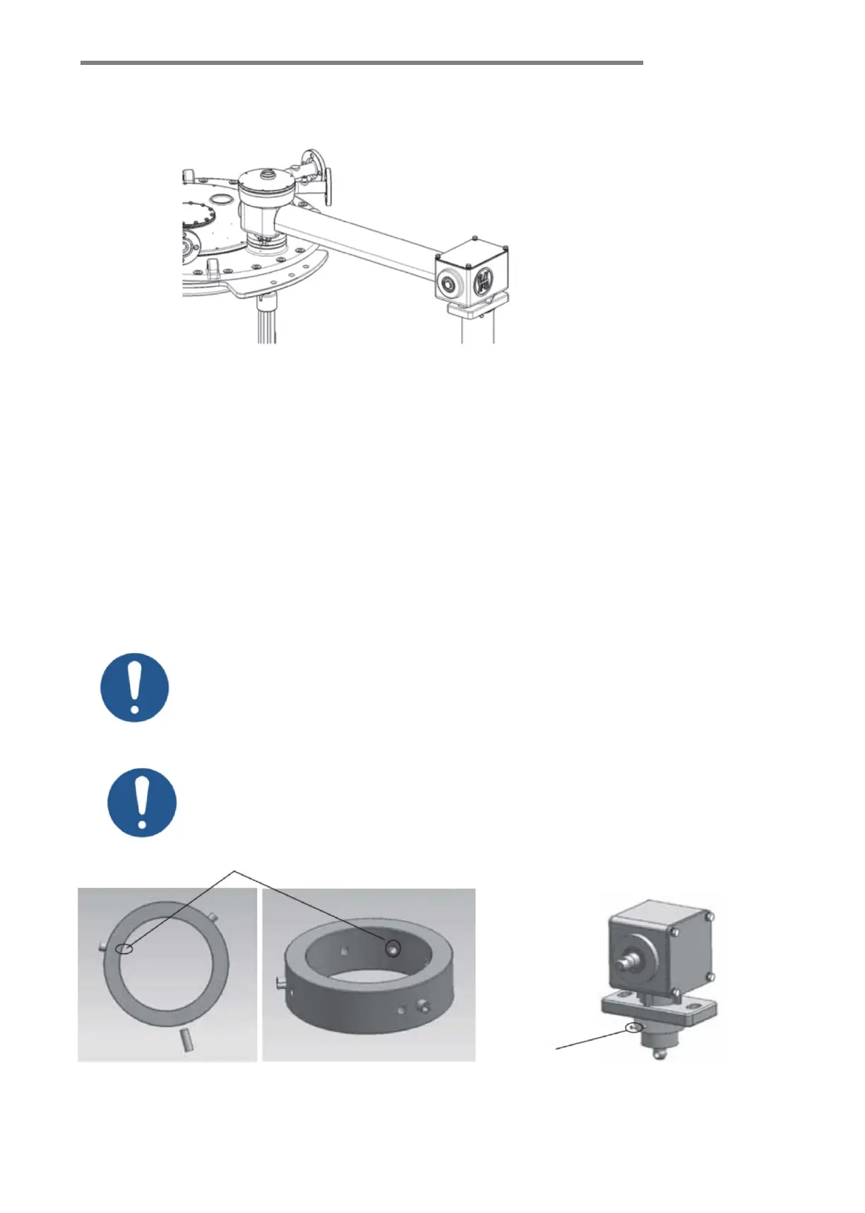
9.6 Installation of driving shaft shield cover
9.6.1 Installation of horizontal shield cover
The length of the horizontal shield is determined by the design of the transformer manufacturer. After
installation of the driving shaft, put the clamps on both ends of the horizontal shield covers (provided in the
accessories), then clamp them on the protruding platform of the gear box and the bevel gear box, and finally
move the clamps to the protruding platform positions on both sides, tighten and firm. (See Figure-9-5)
9.6.2 Installation of vertical shield cover (See Figure-9-6)
9.6.2.1 Fix 3 stainless steel 6×16 straight pins on the bushing HM8210.303.3 (120° equally divided), and
protrude the outer diameter of the bushing about 5mm, and the inner diameter positions should not be
protruded. (See Figure-9-6)
9.6.2.2 Place the bushing HM8210.303.3 at the lower end of the bevel gear box and fix with 4 pieces of
M6×10 set screws (90° equally divided). (See Figure-9-7)
Straight pins not protruded the inner diameter
Figure-9-6 Figure-
9-7
When the length of the vertical drive shaft exceeds 2m, a middle support box is
Incorrect adjustment of the gear box can cause damage to the tap-changer! The
gear box can only be adjusted when the pressure ring is loosened. It must not
rotate when it is adjusted. Only turn the drive shaft to adjust the gear box.