36
8.1.2.2.1 Pass kerosene vapor into on-load tap-changer
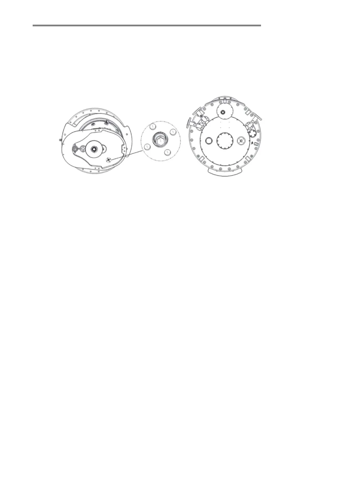
The pipe joints R and Q on the tap-ch
anger head (See Figure-8-3) for the position of the pipe joint on
the tap-changer head) are connected to the connecting pipe, and the inner diameter is at least 50mm to
connect to kerosene vapor.
Figure-8-2
8.1.2.2.2 Drying
a.
Pass in kerosene vapor around 90℃ and keep this temperature constant for 3 to 4 hours.
b. Increase the kerosene gas temperature at a rate of 10°C/hour till the specified final temperature, but the
maximum temperature of the tap-changer cannot exceed 125°C.
c. In vacuum drying, the temperature on the tap-changer is 105°C to a maximum of 125°C. The highest
residual pressure is 133Pa. The drying duration is the same as the transformer, but at least 50 hours.
8.1.2.2.3 To remove the diverter switch insert, close the oil drain bolt.
a. To remove the diverter switch insert according to section 6.2.4.
b. Turn on the oil drain bolt clockwise with an extended T-wrench. (See Figure-8-3) (Torque 20 N.m.)
8.1.2.2.4 After tightening the oil drain bolt, reinstall the on-load diverter switch insert. Install the on-load
diverter switch insert according to chapter 6.2.6.
8.2 Oil filling
After drying, in order to prevent too much moisture from entering the oil compartment, the oil
compartment (diverter switch insert already installed) should be refilled with oil as soon as possible.
The top cover of the tap-changer should be closed again and 24 pieces of M10 bolts should be tightened,
paying attention to the correct position of the sealing O-ring. Both the transformer and the diverter switch
are filled with oil under vacuum. In order to vacuumize the diverter switch oil compartment and the
transformer simultaneously, the by-pass pipe accessories provided by our factory can be installed between
oil filling flange on the tap-changer head and oil-overflow flange of the transformer.
Fill the tap-changer with new transformer oil up to the same level as in the transformer tank. Thus, install the
Figure-8-3