30
After tightening it by the M10 connecting nuts which provide with tap changer, the washer of shield cover
should be turned up 90° in two sides. (Figure-6-19)
6.5.2 The terminal lead of tap selector shall not deform or damage the tap changer
6.5.2.1. The lead wire of voltage regulating winding of transformer shall be led to tap selector from both sides
to avoid distortion of tap selector due to stress on one side lead wire.
6.5.2.2. The connection between the tap selector terminal and the terminal clamp of the transformer lead should
have a certain deflection, which should not be too short, and the connection should be soft. It is recommended
that this section of connection should not be coated with insulating paint, so as to avoid hardening and
deformation of the insulating rod after drying.
6.5.2.3. The lead end connecting the tap selector shall be connected according to the expanded ring shape
(looping), so that the insulating board of the tap selector is not subject to tension.
6.5.2.4. The tap selector terminal lead shall be led out from the outside of the selector and shall never pass
through the inside of the selector.
6.5.2.5 The terminal lead of the change-over selector should be led out from the outside of the change-over
selector insulating rod, and there must be enough clearance between the lead and the insulating rod of the tap
selector’s moving contact to prevent the movement of the change-over selector from being blocked.
6.5.2.6 The bell-type tap-changer must be lifted 5 to 20mm after the lead is connected. For this reason,
special attention should be paid to the tightness of the connecting lead. It is recommended that the
intermediate flange be installed on the supporting structure, and the intermediate flange should be
temporarily raised by using a pad until the final installation finishes. Then connect the lead (same as the
actual installation situation). After the lead is completed, remove the pad and check the tightness of the lead
and whether the tap-changer is under force.
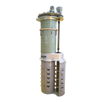
Figure-6-19 This diagram only shows how to install, for example the SHZV1000 has two mounting holes,
other models are also available in customised designs, please follow this diagram when installing according
to the actual situation.