9
ZCT9050CE Rev. C (01/25)
Operation
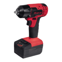
The Snap-on Cordless Impact Wrench is ideal for a wide
variety of fastener turning jobs in both the industrial and
automotive fields. When used with Snap-on impact
sockets, it provides power and speed for greater job
efficiency with less operator fatigue. The impact wrench
also adds the freedom of movement not usually available
with products requiring air hoses or electrical cords.
Application
Friction Ring Anvil
1. When installing an impact socket, place the forward/
reverse bar in the center position to avoid accidental
starting of the tool; or remove the battery pack.
2. Align the square of the socket with four flats at the
end of the anvil.
3. Push the socket over the friction ring, until it comes
to a stop.
4. To remove the impact socket, grip the socket firmly
and slip off the anvil.
This type of anvil is suitable for exchanging sockets regularly,
like in a garage environment.
Pinned Anvil
1. When installing an impact socket, place the forward/
reverse bar in the center position to avoid accidental
starting of the tool; or remove the battery pack.
2. Align the hole on the socket with the pin on the anvil.
3. Align the squares together and push socket onto the
anvil until the pin is in the hole of the socket.
4. To remove the impact socket, use a pointed object to
depress the pin through the hole. Then slide off the
impact socket.
This type of anvil is suitable for industrial usage, such as an
assembly line.
Using the Speed Selector
The speed selector button is used to control the anvil
speed, impact speed, and torque output.
Figure 2: Speed Selector
The speed settings can be set independently for CCW
(reverse) and CW (forward). This feature can be used to
remove fasteners with full speed and reinstall them with
improved control at a lower speed.
1. Pull and release trigger to activate tool. The current
speed selection will be shown according to the speed
selector chart shown below.
2. Push the speed selector to cycle through the three (3)
speed modes. When the desired speed setting is lit,
begin work.
SPEED
SETTING
SPEED
SELECTION
DISPLAY
SPEED IPM
TORQUE
% *
1
0-870 0-560 0-25%
2
0-1300 0-1150 0-50%
3
0-2000 0-2300 0-100%
* Effect on torque % obtained using a 1-1/4” hex bolt.
Always use a torque wrench to verify torque.
LIGHT COLOR DIRECTION
Green CCW (reverse)
Red CW (forward)
Forward/Reverse Switch
The forward/reverse switch determines the rotating
direction of the anvil, either clockwise or
counterclockwise.
A
B
Figure 3: Forward/Reverse Switch
A. Depress switch for reverse or
counterclockwise rotation.
B. Release switch for forward or clockwise
rotation.
To change the direction of anvil rotation:
1. Be sure the impact wrench is stopped and not
operating.
2. The position of the forward/reverse switch
determines the direction of the anvil rotation. Switch
positions, when tool is positioned as above, are:
— Forward (B), the anvil rotates clockwise,
— Reverse (A), the anvil rotates counterclockwise.