Page 8
B. Remove the hardware that secures the machine to
the pallet and slide the balancer onto the floor where it is
to be installed.
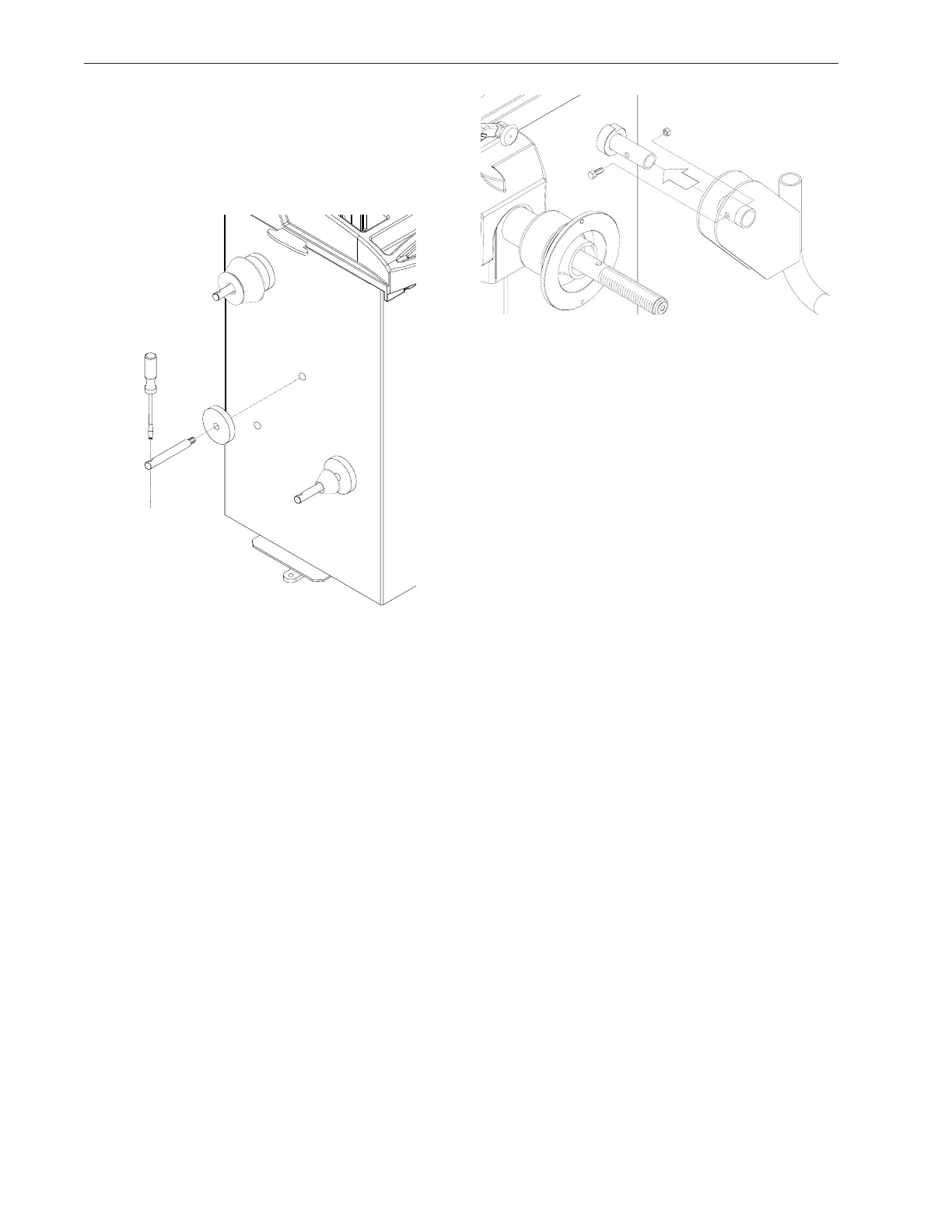
C. Install the accessory pins (Figure 7). Tighten firmly.
Figure 7
D. Place cones and other accessories onto the acces-
sory pins.
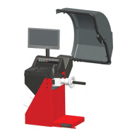
2.2 HOOD GUARD INSTALLATION
The safety hood guard is standard equipment and
must be installed prior to use.
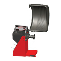
Refer to Figure 8 for hood guard installation.
Parts Required:
(1) Hood Guard Assembly
(1) 3/8” - 16 x 2” HHCS
(1) 3/8” x 16 Keps
Position the hood guard in the raised (up) position.
Slide the hood guard support tube over the frame pivot
shaft protruding from the right side of the balancer cabi-
net.
Line up the mounting holes in both the pivot shaft and
the guard support tube. Secure the guard with 3/8” hard-
ware.
Figure 8
2.3 ELECTRIC INSTALLATION
ANY ELECTRICAL WIRING MUST BE PER-
FORMED BY LICENSED PERSONNEL.
ALL SERVICE MUST BE PERFORMED BY AN
AUTHORIZED SERVICE TECHNICIAN.
Check on the plate of the machine that the electrical
specifications of the power source are the same as the
machine. The machine uses 115VAC, 50-60Hz, 1Ph,
8.0 Ampere. 230VAC units are available if required.
NOTE:
Any electrical outlet installation must be verified
by a licensed electrician before connecting the bal-
ancer.
NOTE:
This machine performs a self-test routine on start-
up. There will be a delay of several seconds before
the display is activated.