10 Snap-on Tools Corporation Kenosha, WI 53141-1410
PROCESS SELECTION (Cont.)
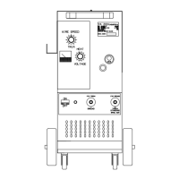
L. TORCH PANEL MOUNT
Combination power output, con-
tactor switch connection, gas
supply connection, and wire feed
output in a single unit.
M. CONTROL RECEPTACLE (OUTPUT)
Output receptacle for wire feed
voltage, trigger circuit and
wire speed control out to the
remote feed unit.
N. (+)POSITIVE TERMINAL
Positive output terminal from
the welder DC power source. The
Power plug is inserted into this
terminal for standard welding
operation. The work cable can be
plugged into this terminal for
straight polarity welding on
very light sheet metal, or for
using flux cored gasless wire.
WELDING
Optimum control settings will
vary according to the thickness of
the metal, the type of joint,
operator preference, etc. Best
results can be obtained through
experience with the welding machine
or by making trial welds. Select
some sample material of the same
type and thickness as the material
to be welded. Set the welding
controls(using the parameter chart
located on the door of the feed unit
or on page 25) for optimum results
using the sample material thickness
and wire size being used as a
starting point, weld until experi-
ence is gained using the unit.
CONTINUOUS WELDING ON
STEEL
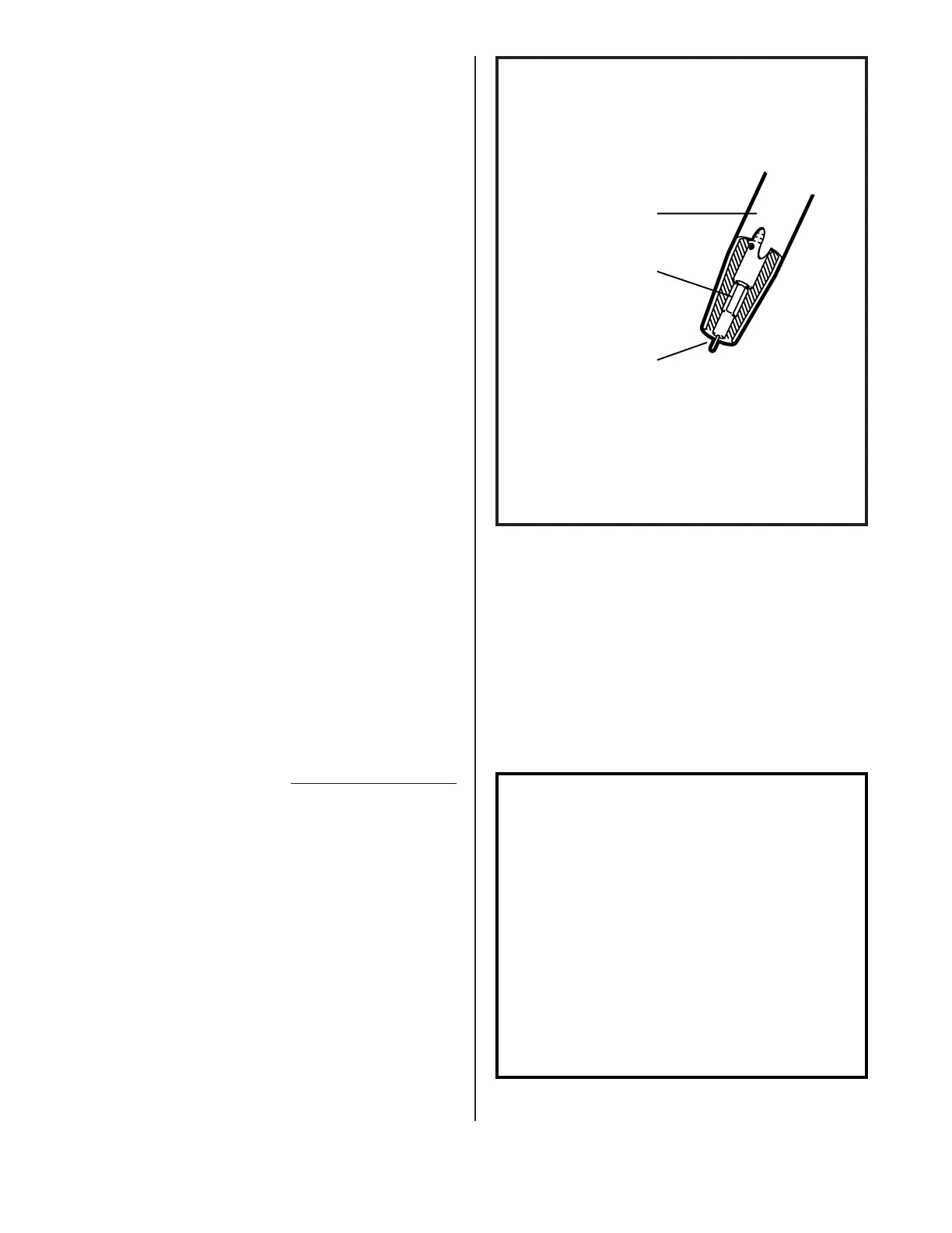
1. Trim the electrode wire to leave
approximately 1/4 inch stickout
beyond the end of the contact tip
and install the welding nozzle.
The contact tip should be flush
or stick out up to 1/16 inch
beyond the end of the nozzle.
2. Spray the inside of the nozzle
and the outside of the contact
tip with anti-spatter compound.
3. Locate the torch over the joint
to be welded with the contact tip
approximately 3/4 inch from the
work surface.
4. Use a welding helmet with a shade
9 to 11 filter lens, depending on
operator preference.
NOTE
When welding steel, the ideal
position for holding the torch
is inclined approximately 30
degrees towards the direction
of travel. This allows the arc
to be seen easily, resulting
in greater control of the weld
pool. Most right-handed wel-
dors move from left to right.
This method, known as forehand
welding, provides a gas shield
for the cooling weld puddle
and helps in obtaining an
oxidation free weld deposit.
NOZZLE
CONTACT TIP
(FLUSH TO
1/16" STICKOUT)
ELECTRODE WIRE
(1/4" STICKOUT)
FIG. 12. NOZZLE ADJUSTMENT
FOR WELDING STEEL
 Loading...