18 Snap-on Tools Corporation Kenosha, WI 53141-1410
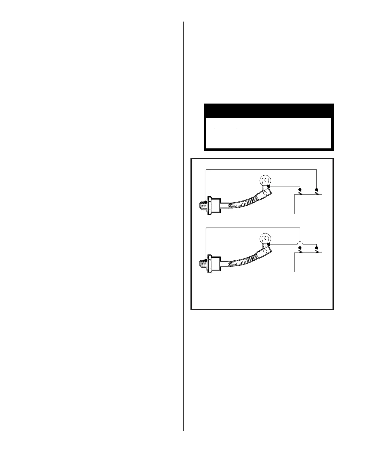
12 VOLT
BAT-
TERY
DIODE
12 VOLT
LIGHT BULB
12 VOLT
BAT-
TERY
12 VOLT
LIGHT BULB
DIODE
+-
+-
TESTING AND REPLACING DIODES
Silicon diodes have proven to be
highly reliable. However, weld
spatter build-up in the torch can
short out and cause diode overload
and consequent failure. The follow-
ing information is provided as a
guide should a failure be sus-
pected.
Silicon diodes exhibit two main
fault conditions:
1. "Open Circuit" - causes a reduc-
tion in welder output.
2. "Short Circuit" - causes the
circuit breaker to trip.
If a fault is suspected, the diode
may be tested as follows:
1. Remove the top connection of
each diode to be tested.
2. Using a Volt-Ohm Meter set on
RX1K, check for continuity
through the diode in both direc-
tions. If there is no continuity
in either direction, the diode
is in "open circuit" condition
and must be replaced. If there
is continuity in both direc-
tions, the diode is in "short
circuit" condition and must be
replaced. If there is continu-
ity in one direction only, the
diode is functioning properly.
3. If all the diodes check out
satisfactorily with the Volt-
Ohm Meter, a load check must be
made. This is easily accom-
plished using a twelve volt
battery and a twelve volt light
bulb connected as shown. Again
test for electrical current flow
in both directions. The bulb
should light in one (1) direc-
tion only - not both.
CAUTION
NEVER use a "megger" or a
high voltage device to test
a diode.
4. When replacing diodes, it is
very important that a heat con-
ductive compound (Radio Shack
#276-1372) be used where the
diode makes contact with the
aluminum heat sink. Do not
grease the threads on the diode.
FIG. 18. DIODE LOAD CHECK CONNECTION
DIAGRAM - TEST FOR FLOW IN BOTH
DIRECTIONS


 To Next Page