Section 4 - ADJUSTMENT & REPAIR
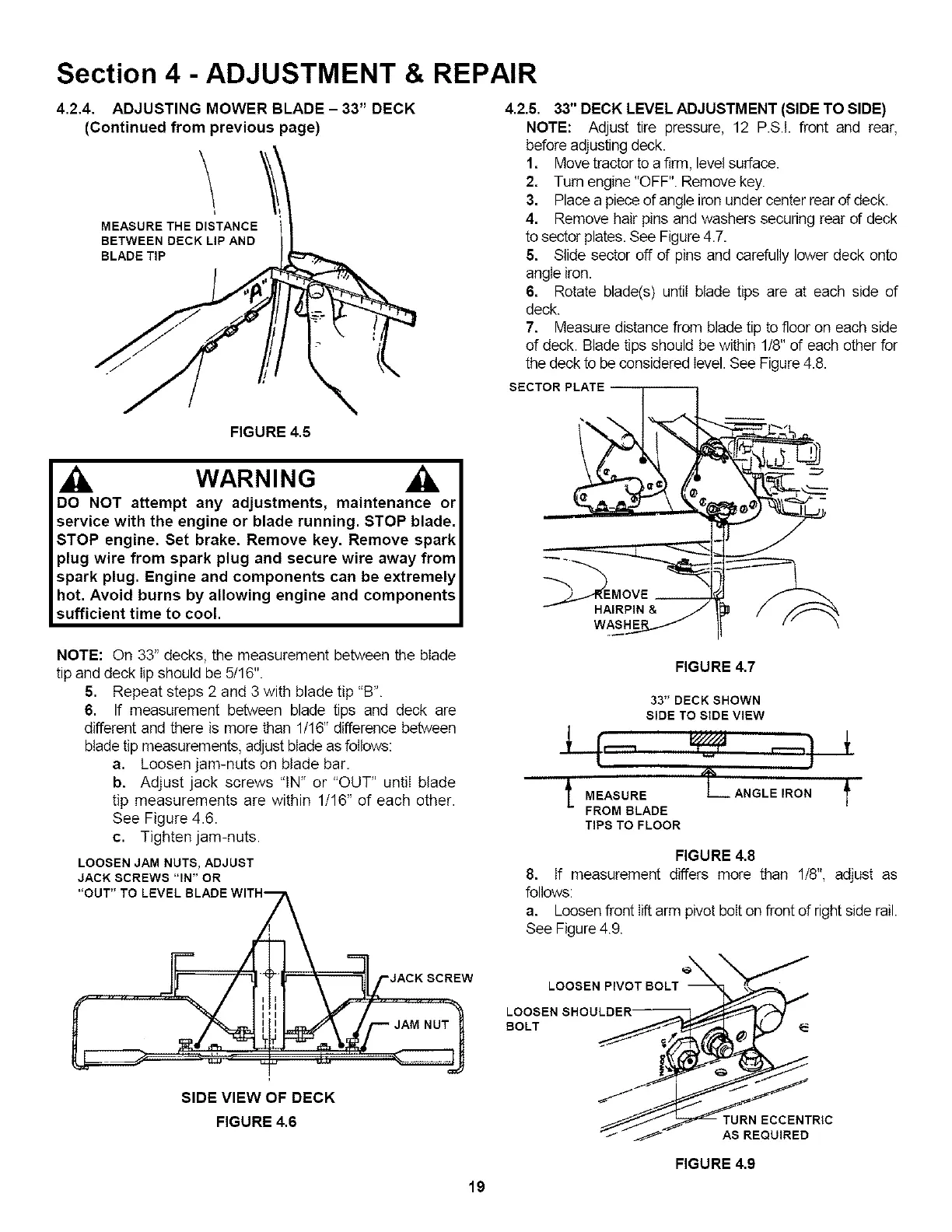
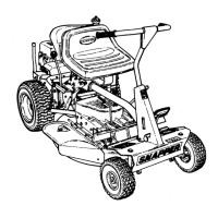
4.2,4, ADJUSTING MOWER BLADE- 33" DECK
(Continued from previous page)
\
MEASURE THE DISTANCE
BETWEEN DECK LIP AND
BLADE TIP
4.2.5. 33" DECK LEVEL ADJUSTMENT (SIDE TO SIDE)
NOTE: Adjust tire pressure, 12 P.S.I. front and rear,
before adjusting deck.
1. Move tractor to a firm, level surface.
2. Tum engine "OFF". Remove key.
3. Place a piece of angle iron under center rear of deck.
4. Remove hair pins and washers securing rear of deck
to sector plates. See Figure4.7.
5. Slide sector off of pins and carefully lower deck onto
angle iron.
6. Rotate blade(s) until blade tips are at each side of
deck.
7. Measure distance from blade tip to floor on each side
of deck. Blade tips should be within 1/8" of each other for
the deck to be considered level. See Figure4.8.
SECTOR PLATE
FIGURE 4,5
WARNING
DO NOT attempt any adjustments, maintenance or
service with the engine or blade running. STOP blade.
STOP engine. Set brake. Remove key. Remove spark
plug wire from spark plug and secure wire away from
spark plug. Engine and components can be extremely
hot. Avoid burns by allowing engine and components
sufficient time to cool.
HAIRPIN &
NOTE: On 33" decks, the measurement between the blade
tip and deck lip should be 5/16".
5. Repeat steps 2 and 3 with blade tip "B".
6. If measurement between blade tips and deck are
different and there is more than 1/16" difference between
blade tip measurements, adjust blade as follows:
a. Loosen jam-nuts on blade bar.
b. Adjust jack screws "IN" or "OUT" until blade
tip measurements are within 1/16" of each other.
See Figure 4.6.
c. Tighten jam-nuts.
LOOSEN JAM NUTS, ADJUST
JACK SCREWS "IN" OR
"OUT" TO LEVEL BLADE WITH ,
"4 JACK SCREW
I I JAM NUT
SIDE VIEW OF DECK
FIGURE 4,6
19
FIGURE 4,7
33" DECK SHOWN
SIDE TO SIDE VIEW
t MEASURELANGLE,RONf
FROM BLADE
TIPS TO FLOOR
FIGURE 4,8
8. If measurement differs more than 1/8", adjust as
follows:
a. Loosen front lift arm pivot bolt on front of right side rail.
See Figure 4.9.
LOOSEN PIVOT BOLT _ X_ "_I"
FIGURE 4,9