EasyManuals Logo
Home>Snapper>Lawn Mower>G Series

Snapper G Series User Manual

Snapper G Series
44 pages
To Next Page IconTo Next Page
To Previous Page IconTo Previous Page
Page #33 background imageLoading...
Page #33 background image
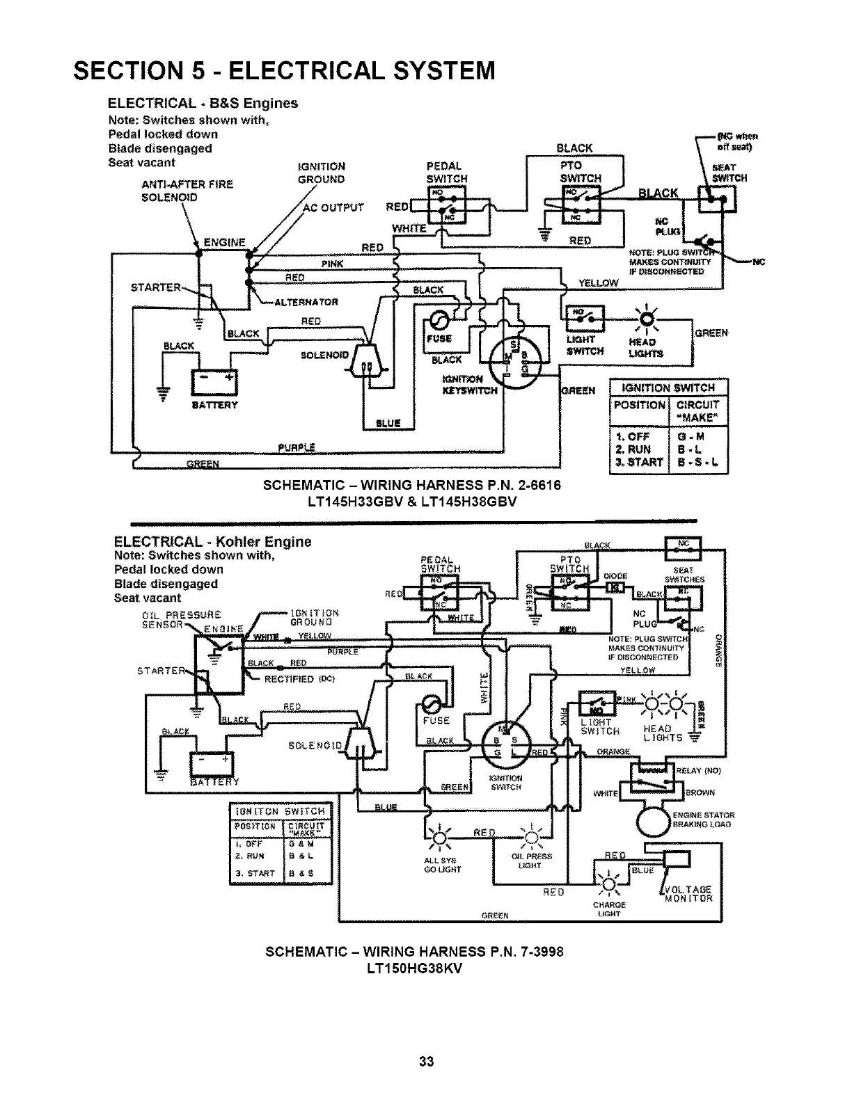
SECTION 5 - ELECTRICAL SYSTEM
ELECTRICAL +B&S Engines
Note: Switches shown with,
Pedal locked down
Blade disengaged
Seat vacant
ANTI-AFTER FiRE
$OLENOtD
IGNITION PEDAL
GROUND SWITCH
BLACK
RED
SCHEMATIC -WIRING HARNESS P.N. 2-6616
LT145H33GBV & LT145H38GBV
ii
ELECTRICAL * Kohler Engine
Note; Switches shown with,
Pedal locked down
Blade disengaged
Seat vacant
OIL PRESSURE _ _TIoN
SENSOr"
IGNITION SWITCN
POSITION ClRCUfT
=MAKE"
I. OFF G - M
2_ RUN B - L
&START B.E+L
SCHEMATIC - WIRING HARNESS P.N, 7-3998
LT150HG38KV
33

Table of Contents

Other manuals for Snapper G Series

Questions and Answers:

Question and Answer IconNeed help?

Do you have a question about the Snapper G Series and is the answer not in the manual?

Snapper G Series Specifications

General IconGeneral
BrandSnapper
ModelG Series
CategoryLawn Mower
LanguageEnglish

Related product manuals