© Trynex International 2009 L1040
7 — 20
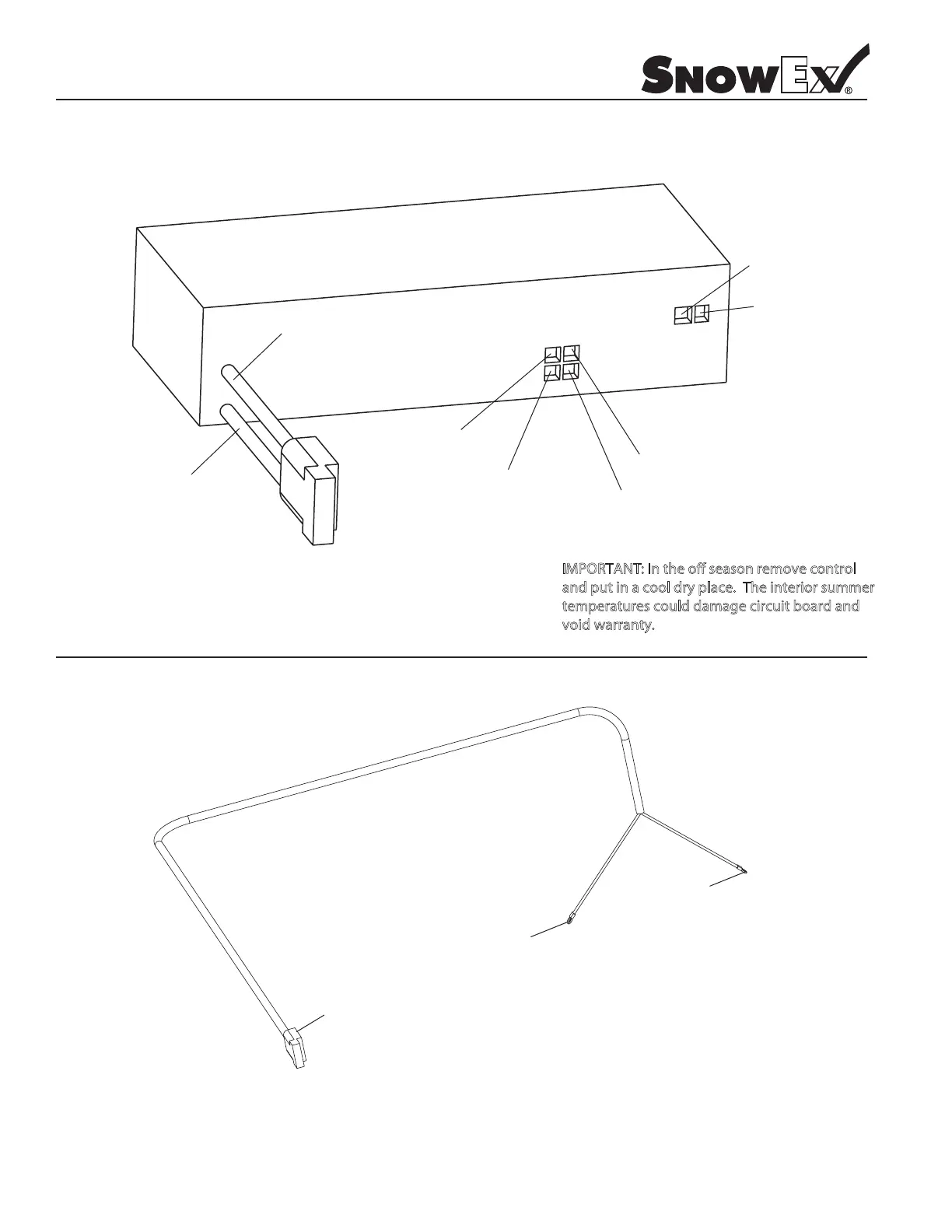
Control Wiring Diagram
Model # SP-1875
Black
Negative (–)
Auger
Red Positive (+)
Auger
Black Negative (–)
Spinner
Red Positive (+)
Spinner
Black Negative (–)
INPUT
OUTPUT
Red
Positive (+)
Vibrator
Black Negative (–)
Vibrator
Red Positive (+)
Connect to control
mating half
Positive
White with Red Tracer (+) to battery
Ring Terminal
Negative
Black (–) to battery
Ring Terminal
* NOTE:
A) Leads must only be attached to battery.
B) If fusing, must use minimum 60 Amp
Maxi type fuse or circuit breaker.
D6341 Control Power Cable
M O A ov o
a p a o p o
p a ag bo
vo a a