19
EN
ATySController A15 - 549779A - SOCOMEC
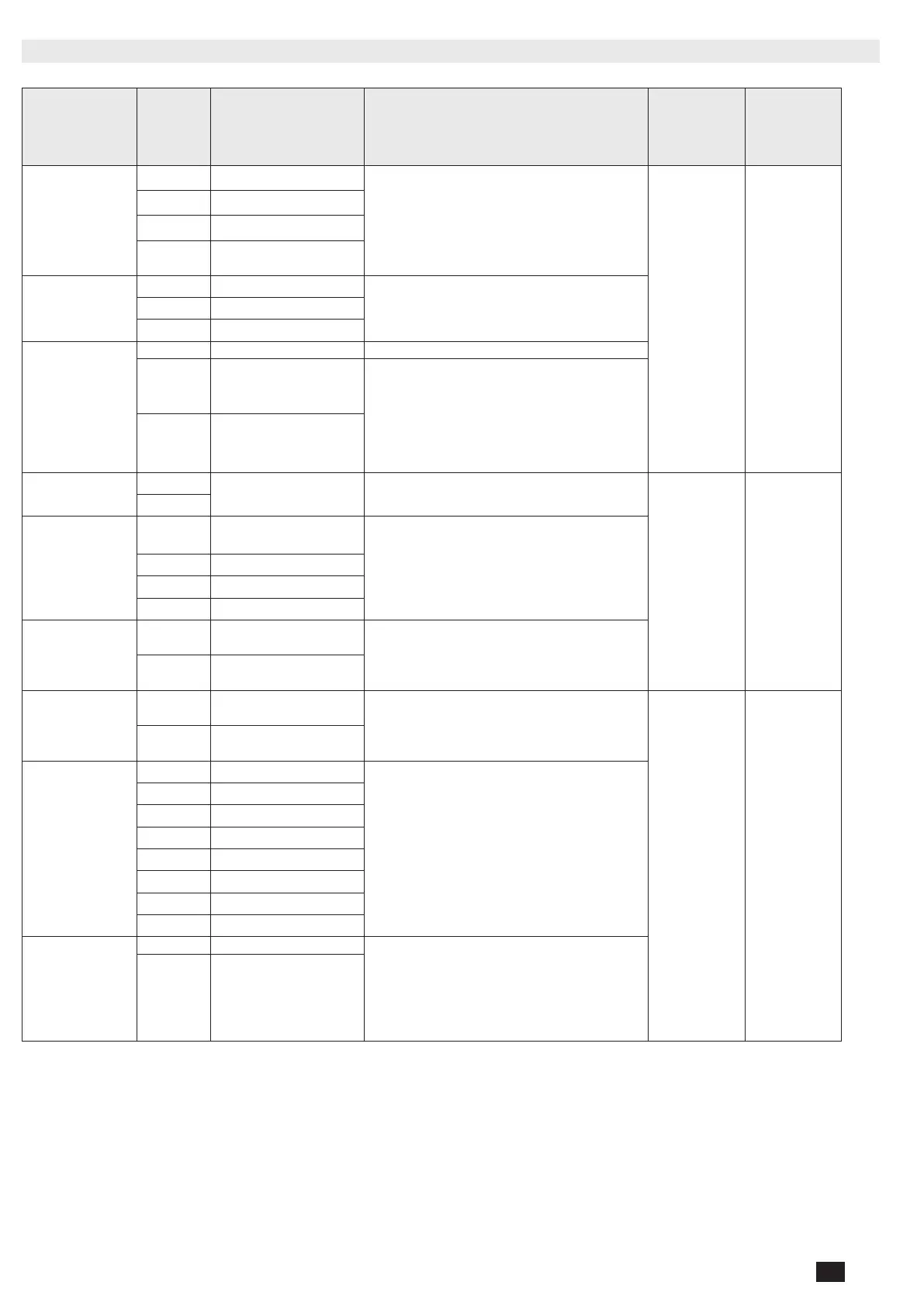
9.4. Terminal denomination, description and characteristics
Denomination Terminal Description Characteristics
Recom-
mended
Cable section
Tightening
torque /
screw type
Control signal outputs
(orders to RTSE)
14 Position II order
AC1 – General use – Ie: 5A , Ue: 250 V.a.c
DC1 – General use – Ie: 5A , Ue: 30 V.d.c
AC15 - Ie: 3A, Ue: 120 V.a.c
AC15 - Ie: 1.5A, Ue: 240 V.a.c
DC13 - Ie: 0.22A, Ue: 125 V.d.c
DC13 - le: 0.11A, Ue: 250 V.d.c
1-2.5mm² 0.58 Nm
15 Position I order
16 Position 0 order
17
Common point for position
output
RS485
35 NC – Not connected
RS485 Isolated bus36 Negative electrode
37 Positive electrode
Genset output
51 Common point
52
Closed to start the Genset
(closed when controller is
powered off)
AC1 – General use – Ie: 3A , Ue: 250 V.a.c
DC1 – General use – Ie: 3A , Ue: 30 V.d.c
AC15 - Ie 54/51: 3A 52/51: 1.5A Ue: 120 V.a.c
AC15 - Ie 54/51: 1.5A 52/51: 0.75A Ue: 240 V.a.c
DC13 - Ie 54/51: 0.22A 52/51: 0.22 A 125 V.d.c
DC13 - Ie 54/51: 0.11A 52/51: 0.11 A 250 V.d.c
54 Open to start the genset
Controller inhibit input
63A
Controller is inhibited when
this contact is open
Do not use external voltage - Power from common point
0.5-1.5mm² 0.2 Nm/ M2
64A
Return of information
from RTSE (Position
inputs)
70
Common point for position
inputs
Do not use external voltage - Power from common point
71 Position I RTSE
72 Position II RTSE
73 Position 0 RTSE
Fire input
F1
Negative electrode of the 24
V.d.c
12-24 V.d.c
F2
Positive electrode of the 24
V.d.c
Optional Aux supply
24V.d.c
81
Negative electrode of the 24
V.d.c
10-30 V.d.c (Auxiliary supply for controller, does not
supply RTSE)
1-2.5mm² 0.58 Nm / M3
82
Positive electrode of the 24
V.d.c
Source 1 and 2
voltage inputs
103 Source 1 N
Sensing range:
90-520 V.a.c (ph-ph)
50-300 V.a.c (ph-n)
45-65 Hz
Supply:
184-300 V.a.c* (ph-n)
45-65 Hz
Max consumption 10 W
*200-300 V.a.c in maintained mode
104 Source 1 L1
105 Source 1 L2
106 Source 1 L3
203 Source 2 N
204 Source 2 L1
205 Source 2 L2
206 Source 2 L3
DPS output (RTSE
power supply)
301 Phase output
AC – General use – Ie: 6A , Ue: 250 V.a.c
DC – General use – Ie: 6A , Ue: 30 V.d.c
AC15 - Ie: 3A, Ue: 120 V.a.c
AC15 - Ie: 1.5A, Ue: 240 V.a.c
DC13 - Ie: 0.22A, Ue: 125 V.d.c
DC13 - le: 0.11A ,Ue: 250 V.d.c
302 Neutral output
*LiYCY sheilded twisted pair
NOTE 1: Use 7mm as stripping length for the controller terminals
NOTE 2: Use 90°C copper wire for installations with ambient temperature from 35-60°C.
When the ambient temperature is above 60°C, Use 105°C copper wire.
 Loading...