2
Dual auxiliary supply:
Uc 208-277V~ +/-20% 50/60Hz
Power comsumption: 22VA
See instruction sheet
ATS CONTROLLER
To D10
To D20
64B 63B
64B 63B
417 416 415 414 413
207 208 209 210
417 416 415 414 413
207 208 209 210
7172 74
7172 74
ATyS t
Dual auxiliary supply:
Uc 208-277V~ +/-20% 50/60Hz
Power comsumption: 22VA
See instruction sheet
ATS CONTROLLER
ATyS p
Dual auxiliary supply:
Uc 208-277V~ +/-20% 50/60Hz
Power comsumption: 22VA
See instruction sheet
ATS CONTROLLER
ATyS g
Dual auxiliary supply:
Uc 208-277V~ +/-20% 50/60Hz
Power comsumption: 22VA
See instruction sheet
ATS CONTROLLER
To D10
To D20
64B 63B
64B 63B
417 416 415 414 413
207 208 209 210
417 416 415 414 413
207 208 209 210
7172 74
7172 74
ATyS t
Dual auxiliary supply:
Uc 208-277V~ +/-20% 50/60Hz
Power comsumption: 22VA
See instruction sheet
ATS CONTROLLER
ATyS p
Dual auxiliary supply:
Uc 208-277V~ +/-20% 50/60Hz
Power comsumption: 22VA
See instruction sheet
ATS CONTROLLER
ATyS g
1
5
6
4
3 2
1
2
7
104 103
312313 314315 316317 63A64A 24 14 04 13
8 9
10
RJ
102 101
105106
414 413415416417
64B 63B
201 202
205 206204203
210209208207
12
13
14
15
11
1
F1
F2
19
20
16
17
18
23
23
24
24
72 71
74
I/1-2 I/3-4 I/5-6 I/7-8
II/1-2 II/3-4 II/5-6 II/7-8
LOAD
21
22
R1 R2 S1 S2 T1 T2
Opt. 3
Opt. 2
Opt. 1
4
Opt. 4
3
2
1
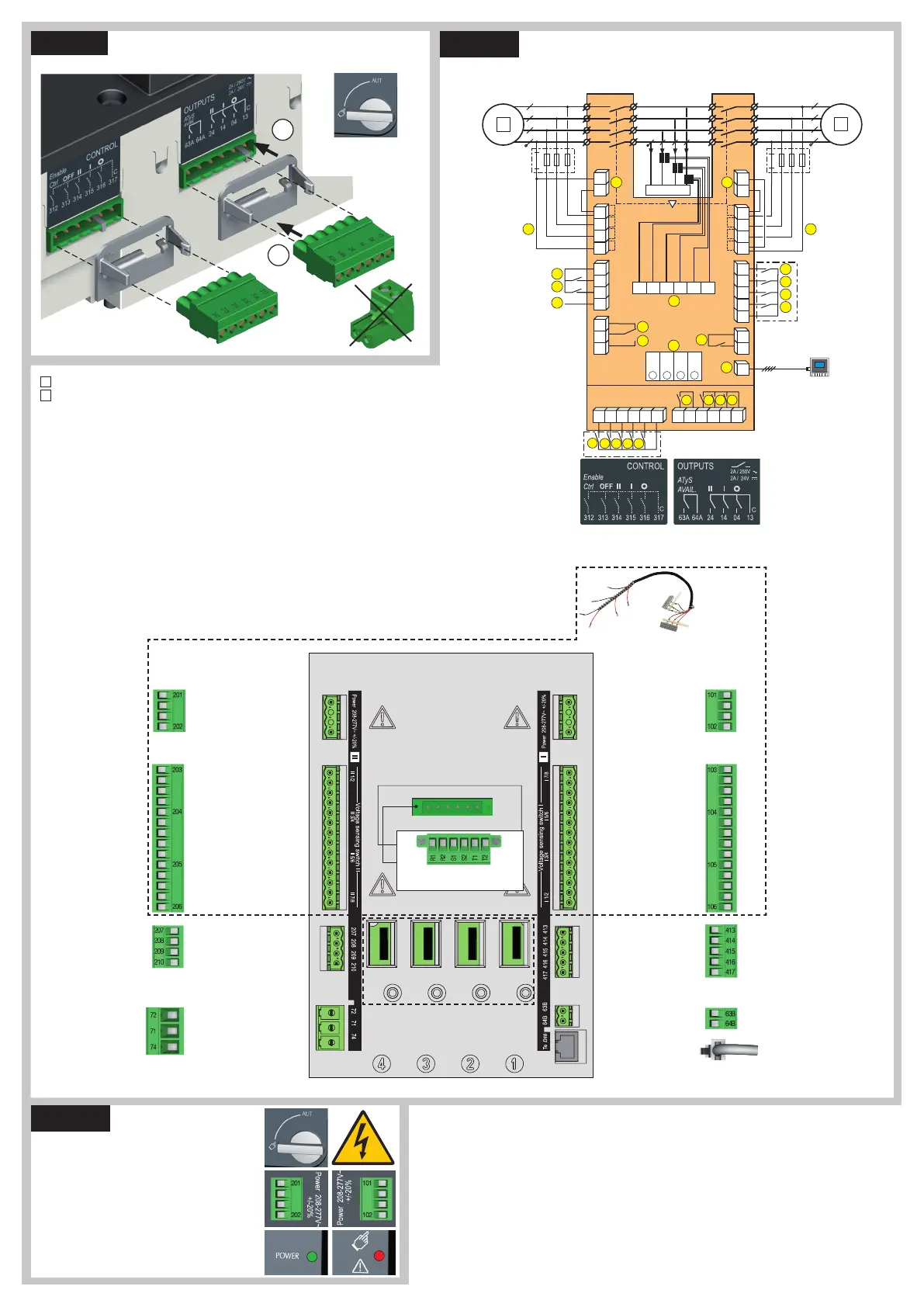
Ensure that the product is in Manual Mode.
CONTROL / COMMAND Terminals
1
preferred source
2
alternate source
1. Position 0 order
2. Position 1 order
3. Position 2 order
4. Zero position priority order
5. Remote Control Enable (Priority
over Auto)
6. Product Available output (Motor)
7. Position II aux contact
8. Position I aux contact
9. Position 0 aux contact
10. O/P to ATyS D20 remote unit
11. Programmable Output Contact.
By default set to ATS Product
Available - Normally Open
12-15. Programmable Inputs 1-4
16-17. Programmable Inputs 5-6
18. Aux. Supply (207/210) to be used
with ATyS optional I/O modules
19. Contact “Start/Stop Genset” : if
S1 is not available the NC contact
(71-72) is close
20. Contact “Start/Stop Genset” : if
S1 is not available the NO contact
(71-74) is open
21. Option Module Slots 1 to 4
22. Current Transformer incoming
cable connections
23. Voltage Sensing Inputs
24. Power Supply Inputs
Power Supply, Sensing and Control wiring (ATS Controller)
Example: Control wiring for a 400 VAC application having a 3 phase and neutral supply.
Slots for optional modules
See on the back "Optional modules"
ATS Module
ControlInputs
(Programmable)
Programmable Inputs
To opt. Module/Common
Progr. Inputs (208-209)
To opt. Module positive
ATS Module
Output Contact
(Programmable)
Genset Start/Stop Signal
NC
Common
NO
Remote interface
RJ45 - to ATyS D20
ATS Voltage
Sensing Input
Source supply I
S I - Phase / Neutral
S I - Phase
S I - Phase
575 VAC (ph-ph) max
S I - Neutral / Phase
332 VAC (ph-n) max
ATS Power Supply
InputI
Power supply I - L/N
Power supply I - N/L
208-277VAC ±20%:
50/60 Hz
Recommanded to use
SOCOMEC Voltage
Sensing Kit
(refer to ATyS p
accessories
for details)
ATS Voltage Sensing
Input
Source supply II
S II - Phase / Neutral
S II - Phase
S II - Phase
575 VAC (ph-ph) max
S II - Neutral / Phase
332 VAC (ph-n) max
ATS Power Supply
InputII
Power supply II - L/N
Power supply II - N/L
208-277VAC ±20%:
50/60 Hz
Current Transformer
incomingcable connections
STEP 5
Check
Whilst in manual mode, check the wiring and if ok
power up the product.
LED “Power” Green: ON
LED Manuel/Fault Red: ON
STEP 3
STEP 4
ATyS D20
Remote Control /
Display Unit
ATyS Voltage
Sensing and
Power supply
Kit excludes the
need for fuses
F1 & F2.
Connect the product with a cable of section of 1,5 to 2,5 mm
2
.
Screw M3 - Tightening torque:
min.: 0.5 Nm - max.: 0.6 Nm / min.: 4.43 lbin - max.: 5.31 lbin

 Loading...


