x 4
1
SETUP
2
VOLT. LEVELS
3
FREQ. LEVELS
4
PWR. LEVELS
5
TIMERS VALUE
6
I-O
7
COMM
8
DATE/TIME
NETWORK 4NBL OV. U I 115% OV. F I 105% OV.P I 0000 kVA 1FT 0003 SEC IN 1 --- NO DHCP NO (9) YEAR
AUTOCONF NO (7) OV. U HYS I 110% OV. F HYS I 103% OV.P HYS I 0000 kVA 1RT 0180 SEC IN 2 --- NO IP 1-2 192.168.
(9)
MONTH
NEUTRAL AUTO UND. U I 085% UND. F I 095% OV.P I I 0000 kVA 2FT 0003 SEC IN 3 --- NO IP 3-4 .002.001 DAY
ROT PH. --- UND. U HYS I 095% UND. F HYSI 097% OV.P HYS I I 0000 kVA 2RT 0005 SEC (2) IN 4 --- NO GAT1-2 000.000. HOUR
CHECK ROT YES UNB. U I 00% OV. F I I 105% 2AT 0005 SEC (1) IN 5 --- NO GAT3-4 .000.000
(9)
MINUTE
NOM. VOLT 400 V UNB. U HYS I 00% OV. F HYS I I 103% 2CT 0180 SEC (1) IN 6 --- NO MSK1-2 255.255. SECOND
NOM. FREQ 50 Hz OV. U I I 115% UND. F I I 095% 2ST 0030 SEC (1) IN 7 --- NO (8) MSK3-4 .255.000
(9)
APP M-G OV. U HYS I I 110% UND. F HYS I I 097% ODT 0003 SEC IN 8 --- NO (8) ADDRESS 005
PRIO TON NO (1) UND. U I I 085% TOT UNL (1) IN 9 --- NO (8) BDRATE 9600
PRIO EON NO (3) UND. U HYS I I 095% TOT 0010 SEC (1) IN10 --- NO (8) STOP BIT 1
PRIO NET 1 (2) UNB. U I I 00% T3T 0000 SEC (1) IN11 --- NO (8) PARITY NONE
RETRANS NO UNB. U HYS I I 00% TFT UNL (1) IN12 --- NO (8)
RETURN 0 NO TFT 0600 SEC (1) IN13 --- NO (8)
CT PRI 100 E1T 0005 SEC (3) IN14 --- NO (8)
CT SEC 5 E2T UNL (3) OUT 1 POP NO
S1=SW2 NO E2T 0010 SEC (3) OUT 2 --- NO (8)
BACKLGHT INT E3T 0005 SEC (3) OUT 3 --- NO (8)
CODE P 1000 E5T 0005 SEC (4) OUT 4 --- NO (8)
CODE E 0000 E6T LIM (4) OUT 5 --- NO (8)
BACKUP SAVE E6T 0600 SEC (4) OUT 6 --- NO (8)
E7T 0005 SEC (4) OUT 7 --- NO (8)
LST 0004 SEC (5) OUT 8 --- NO (8)
EET 0168 H (6) OUT 9 --- NO (8)
EDT 1800 SEC (6)
17
14
Modbus RS485
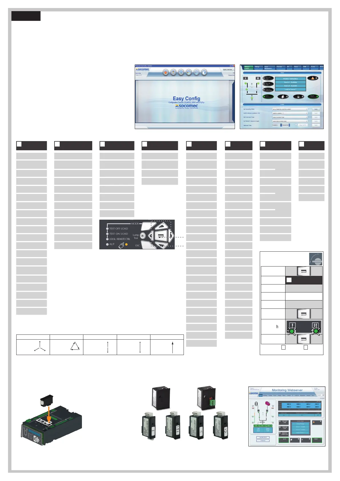
Programming the ATyS p
The ATyS p is to be programmed powered up and after wiring verification tests. This may either be done through the front of the ATS Controller using the keypad or with the user-friendly Easy Config
software.
For convenience, we recommend to use the Easy Config software. (Downloadable free from www.socomec.com).
The ATyS p is delivered with default setting values based on most used customer application requirements. The minimum configuration parameters that must be programmed are the type of network
and application together with the voltage and frequency nominal values. ATyS p Auto Configuration makes the setup of Volts, Hz, Phase rotation and Neutral Position quick and easy.
A - Programming with Easy Config Software
To program the ATyS p using Easy Config software simply follow the setting
boxes from left to right until all desired settings in each window have been
completed. Help pop ups are included to show the minimum and maximum
setting values allowed. The software includes most SOCOMEC products so
before programming click NEW and select the product “ATyS p” from the
list of products available.
When the ATyS p is powered and communicating, the software will include
a screen to monitor and display the ATyS p status.
Control through software (such as changing switch position I-O-II) is also
possible when in Super User Mode.
(1) When «APP» is set to «M-G»
(2) When «APP» is set to «M-M»
(3) When one of the I/P is set to «EON»
(4) When one of the I/P is set to «EOF»
(5) When one of the O/P is set to «LSC»
(6) When one of the O/P is set to «EES»
(7) If the product is in manual mode
(8) With optional I/O modules
(9) With Ethernet module
B - Programming with the ATyS p keypad
3 phase / 4 wire 3 phase / 3 wire 2 phase / 3 wire 2 phase / 2 wire 1 phase / 2 wire
4NBL
4BL
N
3NBL
3BL
1
3
2NBL
2
2BL
1BL
Optional Modules
Communication between the software and the ATyS p may be done through the Ethernet/Modbus TCP or Modbus RTU modules that are available as an option. The ETHERNET / MODBUS modules
are to be installed in one of the slots provided in the ATYS p ATS control unit.
Easy Config may be installed on a PC connected through ETHERNET or MODBUS modules for a direct ATyS configuration, either isolated with possibility to create a specific configuration for a later
upload and use in ATyS.
Note: The ATyS p may accept a total of 4 additional Input / Output modules offering an additional 8 programmable inputs and 8programmable outputs. When including a MODBUS module theATySp
accepts a total of 3 I/O modules and when including the ETHERNET module a total of 2 I/O modules.
Refer to the ATyS p accessory section for details.
The Ethernet module
includes a built in Web
Server for Monitoring,
Engine Exerciser Control,
Events...
Extended I/O
2xIP 2xO/P
Modbus
RS485
Pulsed O/P 4-20mA
Ethernet/Modbus
TCP Simple
orGateway
ATyS p devices may also be programmed through the ATS controller keypad.
This programming method is necessary for products not equipped with Ethernet or
Modbus communication modules that facilitate programming through Easy Config
software described above. The keypad is a useful interface and programming
method most especially when changing a few parameters or simply interrogating
the product.
Programming access: Press and hold for 5 s “Validation” push button (17).
Access through the keypad is possible in Automatic or Manual mode, when the
product is in a stable position (I, 0 or II) with at least one supply source available.
Programming is not accessible whilst any cycle sequence is running.
To change the configuration: Enter code (factory code = 1000) using navigation
push buttons (14).
Programming exit: Press and hold for 5 s “Validation” push button (17).
Press 5s
Go To
1
SETUP
Scroll to
AUTOCONF
Enter code
1000
Set to
YES
Press 60 ms
LEDs flash
Save :
press 5s
Setup by Auto Configuration
(Volts, Hz, Neutral pos., Ph rotation)
Note: Source
I
or source
II
must be
available to set by Auto Configuration.
Note 1: Values as listed above are the setting values by default.
Note 2: Ensure that the Default Network Setting and Application match the installation or change accordingly
before using Auto Configuration.
STEP 6

 Loading...


