17
EN
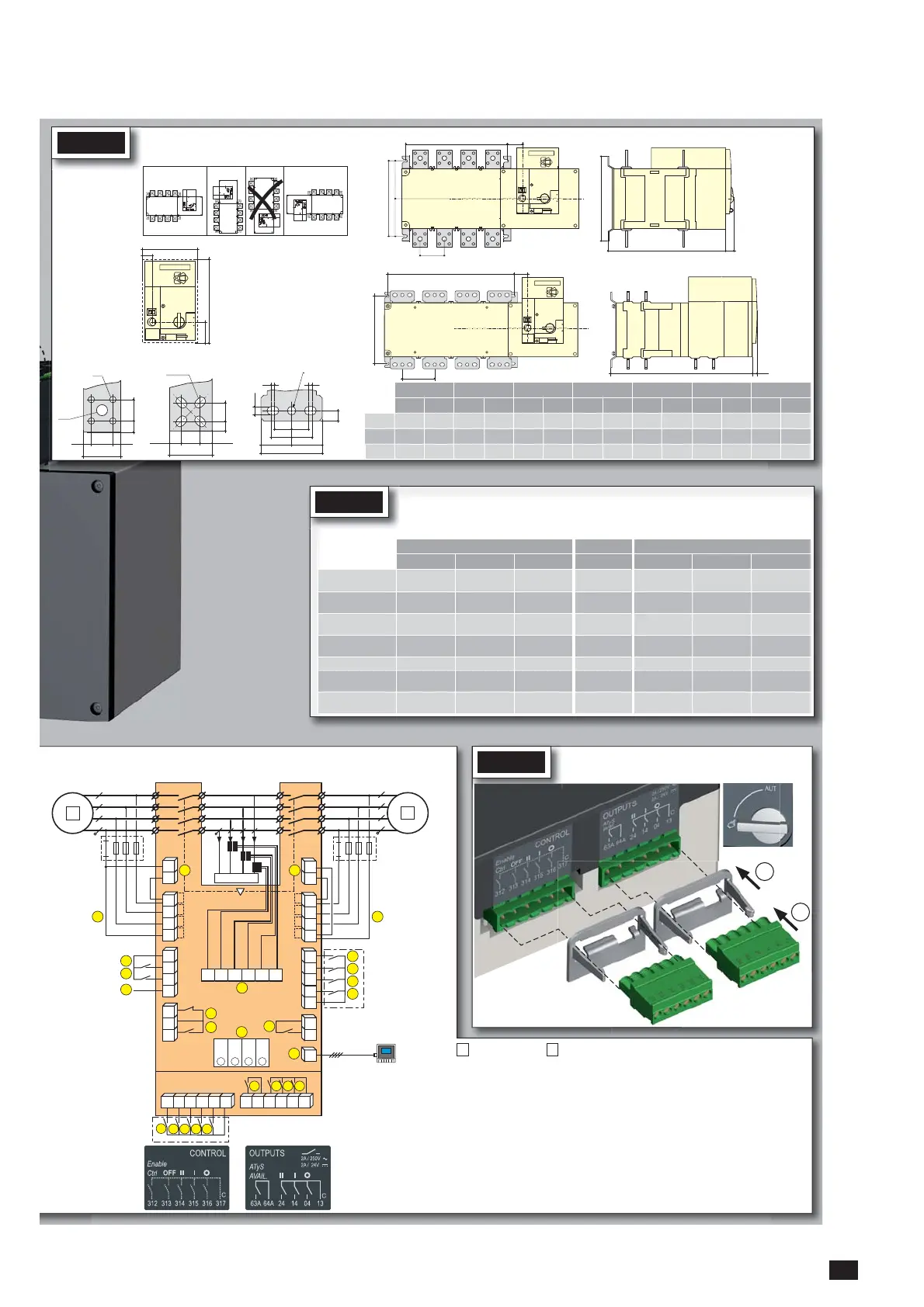
STEP 1
Installation
50.5
20
138
214
ATyS p 1250 AATyS p 800 to 1000 A
ATyS p 800 to 1600 A
ATyS p 2000 to 3200 A
ATyS p 1600 to 3200 A
33 8.58.5
50
3310
ø 9
ø 15
16 x 11
60
28.5 15.7515.75
28.515
15
5
5
12.5
25
25
30
30
45
45
90
ø12.5
Door cut-out for
front panel.
==
250
M
T
51,5
280
C 21
M
T
250
51.5
C21
Dimensions
in mm.
Caution:
Ensure that the
product is installed on
a flat rigid surface.
STEP 3
CONTROL / COMMAND Terminals
Ensure that the product is in Manual Mode.
5
6
4
3 2
1
2
7
104 103
312 313 314 315 316 317 63A 64A 24 14 04 13
8 9
10
RJ
102 101
105106
414 413415416417
64B 63B
72
201
71
202
205 206204203
210209208207
74
12
13
14
15
11
1
F1
F2
19
20
16
17
18
L1 L2 L3 N
L1 L2 L3 N
23
23
24
24
LOAD
21
22
R1 R2 S1 S2 T1 T2
Opt. 3
Opt. 2
Opt. 1
4
Opt. 4
3
2
1
Example: Control wiring for a 400VAC application having a 3 phase and neutral supply.
1
preferred source
2
alternate source
1. Position 0 order
2. Position 1 order
3. Position 2 order
4. Zero position priority order
5.
Remote Control Enable (Priority over Auto)
6. Product Available output (Motor)
7. Position II aux contact
8. Position I aux contact
9. Position 0 aux contact
10. O/P to ATyS D20 remote unit
11. Programmable Output Contact.
By default set to ATS Product
Available - Normally Open
12-15. Programmable Inputs 1-4
16-17. Programmable Inputs 5-6
18. Aux. Supply (207/210) to be used
with ATyS optional I/O modules
19. Contact “Start/Stop Genset” : if S1
is not available the NC contact le
contact (71-72) is close
20. Contact “Start/Stop Genset” : if S1
is not available the NO contact le
contact (71-74) is open
21. Option Module Slots 1 to 4
22. Current Transformer incoming cable
connections
23. Voltage Sensing Inputs
24. Power Supply Inputs
ATyS D20
Remote Control /
Display Unit
1
2
Recommended
orientation
Ok Ok
800 A 1000 A 1250 A 1600 A 2000 A 2500 A 3200 A
3 P 4 P 3 P 4 P 3 P 4 P 3 P 4 P 3 P 4 P 3 P 4 P 3 P 4 P
M 255 335 255 335 255 335 347 467 347 467 347 467 347 467
T 80 80 80 80 80 80 120 120 120 120 120 120 120 120
C 391 391 391 391 391 391 391 391 523 523 523 523 523 523
STEP 2
Power Terminal Connections
To be connected using terminal lugs, rigid or flexable busbars.
FRAME B6 FRAME B7 FRAME B8
800 A 1000 A 1250 A 1600 A 2000 A 2500 A 3200 A
Minimum cable section
Cu (mm
2
) at Ith
2x240 - - - - - -
Minimum cable section
Cu (mm
2
) at Ith
2x50x5 2x60x5 2x80x5 2x100x5
3x100x5 4x100x5 3x100x10
Maximum cable section
Cu (mm
2
)
2x300
4x185 4x185 6x185
---
Maximum Cu busbar
width (mm)
63 63 63 100
100 100 100
Type of screw
M8 M8 M10 M12 M12 M12 M12
Recommended tighten-
ing torque (N.m)
20 20 20 40 40 40 40
Maximum tightening
torque (N.m)
26 26 26 45 45 45 45

 Loading...


