12
EN
ATyS p
Motorised Source Changeover Switch
Automatic Transfer Switching Equipment
STEP 4
Preliminary operations
Check the following upon delivery and after removal of the
packaging:
■ Packaging and contents are in good condition.
■ The product reference corresponds to the order.
■ Contents should include:
Qty 1 x ATyS p
Qty 1 x Emergency handle and fixing clip
Quick Start instruction sheet
Warning
Risk of electrocution, burns or injury to persons and /
or damage to equipment.
This Quick Start is intended for personnel trained in the
installation and commissioning of this product. For further
details refer to the product instruction manual available on
the SOCOMEC website.
■ This product must always be installed and commissioned
by qualified and approved personnel.
■ Maintenance and servicing operations should be
performed by trained and authorised personnel.
■ Do not handle any control or power cables connected to
the product when voltage may be, or may become present
on the product, directly through the mains or indirectly
through external circuits.
■ Always use an appropriate voltage detection device to
confirm the absence of voltage.
■ Ensure that no metal objects are allowed to fall in the
cabinet (risk of electrical arcing).
Failure to observe good enginering practises as well as to
follow these safety instructions may expose the user and
others to serious injury or death.
Risk of damaging the device
■ In case the product is dropped or damaged in any way it
is recommended to replace the complete product.
Accessories
■ Bridging bars and connection kits.
■ Control voltage transformer (400Vac -> 230Vac).
■ DC power supply (12/24Vdc -> 230Vac).
■ Mounting spacers to raise the product x 10mm.
■ Phase barriers.
■ Terminal shrouds / Terminal screens.
■ Auxiliary contacts (Additional).
■ Padlocking in 3 positions (I - O - II).
■ Lockout accessories (RONIS - EL 11 AP).
■ Door escutcheon frame.
■ ATyS D20 Interface (remote control / display unit).
■ RJ45 cable for ATyS D20 => ATyS p.
■ Voltage sensing kit.
■ Current transformers.
■ Plug-in optional modules: RS485 MODBUS communication,
2 inputs/2 outputs, Ethernet communication, Ethernet
communication + RS485 JBUS/MODBUS gateway,
Analogue outputs, Pulse outputs.
For further details refer to the product instruction manual
under chapter "Spares and Accessories"
541 999 C - 02/14 - EN
QUICK START
EN
Clip for
storage of
the
emergency
handle
STEP 3
www.socomec.com
To download, brochures, catalogues and technical manuals:
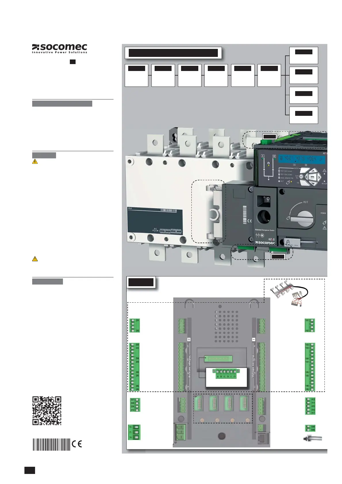
STEP 4
Power Supply, Sensing and Control wiring (ATS Controller)
Connect the product with a cable of section of 1,5 to 2,5 mm
2
.
Screw M3 - Tightening torque: min.: 0.5 Nm - max.: 0.6 Nm
Printing informations: 1 color Black. White paper 90g/m
2
.
Printing size: 420x297. Final size 210x297. This page visible first.
Non contractual document.
Sub
ect to chan
e without notice.
ATS Module
(Programmable)
To opt. Module/Common
Progr. Inputs (208-209)
To opt. Module positive
ATS Module
(Programmable)
NC
Common
NO
RJ45 - to ATyS D20
To D20
64B 63B
417 416 415 414 413
Power 208-277V~ +/-20%
207 208 209 210 7172 74
Power 208-277V~ +/-20%
o o
t.
ro
r. I
o opt.
See on the back "Optional modules"
Recommanded to use SOCOMEC
Voltage Sensing Kit
(refer to ATyS p
accessories
for details)
Power supply I - L
Power supply I - N
50/60 Hz
Power supply II - L
Power supply II - N
50/60 Hz
S II - Phase 1
S II - Phase 2
S II - Phase 3
S II - Neutral
S I - Phase 1
S I - Phase 2
S I - Phase 3
S I - Neutral
STEP 1
Cabinet / Back
Plate Installation
STEP 3
COMMAND /
CONTROL terminal
connections
STEP 2
Power Terminal
Connections
STEP 4
Power SUPPLY and
ATS Controller
Terminal
Connections
STEP 5
CHECK
STEP 6
PROGRAMMING
A - Software
B - Keypad
STEP 7A
AUT Mode
(Automatic Control)
STEP 7C
Manual Mode
STEP 7B
AUT Mode
(Remote Control)
STEP 7D
Padlocking Mode
4.
4.1. Quick Start ATy

 Loading...


