13
EN
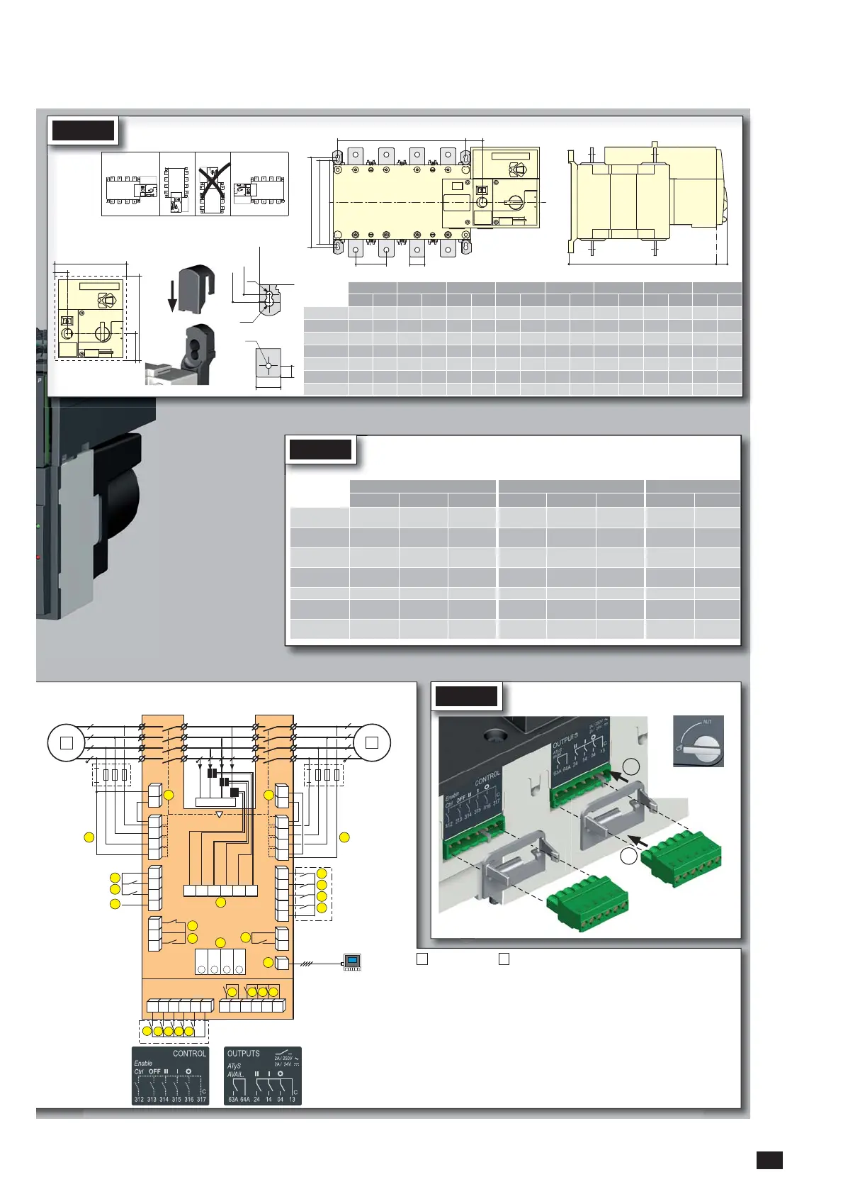
Dimensions in mm.
125 A 160 A 200 A 250 A 315 A 400 A 500 A 630 A
3 P 4 P 3 P 4 P 3 P 4 P 3 P 4 P 3 P 4 P 3 P 4 P 3 P 4 P 3 P 4 P
J 1 34 34 34 34 34 34 35 35 35 35 35 35 34 34 34 34
M 120 150 120 150 120 150 160 210 160 210 160 210 210 270 210 270
T 36 36 36 36 36 36 50 50 50 50 50 50 65 65 65 65
C 244 244 244 244 244 244 244 244 244 244 244 244 320 320 320 320
U 20 20 20 20 20 20 25 25 35 35 35 35 32 32 45 45
W 9 9 9 9 9 9 11 11 11 11 11 11 13 13 13 13
CA 10 10 10 10 10 10 15 15 15 15 15 15 20 20 20 20
M
Fix. 195
Fix. 180
==
J1
UT
C
21
Ø7
Ø9
Fix. 180
Fix. 195
STEP 1
Installation
CA
W
U
Door cut-out for front panel.
50.5
20
138
165
Caution:
Ensure that
the product is
installed on a
flat rigid
surface.
Ok Ok
STEP 3
CONTROL / COMMAND Terminals
Ensure that the product is in Manual Mode.
5
6
4
3 2
1
2
7
104 103
312 313 314 315 316 317 63A 64A 24 14 04 13
8 9
10
RJ
102 101
105106
414 413415416417
64B 63B
72
201
71
202
205 206204203
210209208207
74
12
13
14
15
11
1
F1
F2
19
20
16
17
18
L1 L2 L3 N
L1 L2 L3 N
23
23
24
24
LOAD
21
22
R1 R2 S1 S2 T1 T2
Opt. 3
Opt. 2
Opt. 1
4
Opt. 4
3
2
1
Example: Control wiring for a 400VAC application having a 3 phase and neutral supply.
1
2
1
preferred source
2
alternate source
1. Position 0 order
2. Position 1 order
3. Position 2 order
4. Zero position priority order
5.
Remote Control Enable (Priority over Auto)
6. Product Available output (Motor)
7. Position II aux contact
8. Position I aux contact
9. Position 0 aux contact
10. O/P to ATyS D20 remote unit
11. Programmable Output Contact.
By default set to ATS Product
Available - Normally Open
12-15. Programmable Inputs 1-4
16-17. Programmable Inputs 5-6
18. Aux. Supply (207/210) to be used
with ATyS optional I/O modules
19. Contact “Start/Stop Genset” : if S1
is not available the NC contact le
contact (71-72) is close
20. Contact “Start/Stop Genset” : if S1
is not available the NO contact le
contact (71-74) is open
21. Option Module Slots 1 to 4
22. Current Transformer incoming cable
connections
23. Voltage Sensing Inputs
24. Power Supply Inputs
ATyS D20
Remote Control /
Display Unit
Recommended
orientation
FRAME B3 FRAME B4 FRAME B5
125 A 160 A 200 A 250 A 315 A 400 A 500 A 630 A
Minimum cable sec-
tion Cu (mm
2
) at Ith
50 70 95 120 185 240 2
x
150 2
x
185
Minimum cable sec-
tion Cu (mm
2
) at Ith
--- ---
2x30x5 2x40x5
Maximum cable
section Cu (mm
2
)
50 95 150 150 240 240
2x300 2x300
Maximum Cu busbar
width (mm)
20 20 32 32 32 32
50 50
Type of screw
M8 M8 M8 M10 M10 M10 M12 M12
Recommended tight-
ening torque (N.m)
8.3 8.3 8.3 20 20 20 20 20
Maximum tightening
torque (N.m)
13 13 13 26 26 26 26 26
STEP 2
Power Terminal Connections
To be connected using terminal lugs, rigid or flexable busbars.

 Loading...


