EasyManua.ls Logo

Sofar solar 10K-15KTL-G2 - User Manual

Sofar solar 10K-15KTL-G2
15 pages
Print Icon
To Next Page IconTo Next Page
Loading...
Shenzhen SOFARSOLAR Co.,Ltd.
Product Model:SOFAR 10K-15KTL-G2 (2021.03.17)
ADD: 401, Building 4, AnTongDa Industrial Park, District 68,XingDong Community, XinAn Street, BaoAn
District, Shenzhen, GuangDong.P.R. China
Email: service@sofarsolar.com
Tel: 0510-6690 2300
Web: www.sofarsolar.com
Question and Answer IconNeed help?

Do you have a question about the Sofar solar 10K-15KTL-G2 and is the answer not in the manual?

Summary

Preface

Scope

Describes the assembly, installation, commissioning, and maintenance of inverters.

Target Group

Manual is for qualified support and service personnel.

Symbols Used

Explains safety symbols used in the manual to ensure safety.

Basic Safety Information

Symbols

Details safety-related symbols and their meanings for safe installation.

Safety Instructions and Warnings

Lists essential safety instructions for installation and operation to prevent injury.

Product Characteristics

Intended Grid Types

Lists compatible grid configurations (TN-S, TN-C, TT, IT) for the inverter.

Interface and Dimensions

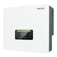
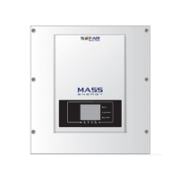
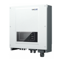
Details the physical interfaces and dimensions of the inverter.

Protection Units

Describes various internal protection mechanisms of the inverter for safe operation.

Installation

Packing Materials

Lists the components and mechanical parts included in the product packaging.

Tools

Enlists the necessary tools required for installation and electrical connections.

Determining the Installation Position

Provides requirements and guidelines for selecting an appropriate installation location.

Installing the SOFAR 10 K~15 KTL-G2

Step-by-step guide for physically mounting and installing the inverter unit.

Electrical Connections

Connecting PGND Cables

Instructions for properly connecting the protective ground (PGND) cables.

Connecting AC Output Power Cables

Details cable selection and steps for connecting the AC output power.

Connecting Communications Cables

Guides on connecting RS485 and other communication cables for data transfer.

Connecting DC Input Power Cables

Provides specifications and procedures for connecting DC input power cables.

DRMs Functions

Explains the Remote Disconnect (DRM) functionality and associated ports.

Commissioning of Inverter

Safety inspection before commissioning

Outlines essential safety checks to perform before starting the inverter.

Start inverter

Procedures for safely starting the inverter after installation and checks.

Operation Interface

Operation and Display Panel

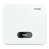
Describes the inverter's operation panel and display functions.

Standard Interface

Details the standard user interface for interacting with the inverter.

Main Interface

Presents the primary user interface screen of the inverter.

Trouble Shooting and Maintenance

Trouble shooting

Provides guidance on identifying and resolving common issues with the inverter.

Maintenance

Outlines recommended maintenance procedures for the inverter.

Decommissioning

Decommissioning steps

Details the procedures for safely removing the inverter from operation.

Package

Information regarding packaging for decommissioned equipment.

Storage

Guidelines for storing the inverter after decommissioning.

Disposal

Instructions for the proper disposal of the inverter.

Technical Data

Input parameter (DC)

Specifies the DC input parameters and electrical characteristics.

Output parameter (AC)

Details the AC output parameters and electrical specifications.

Efficiency, Safety and Protection

Summarizes efficiency ratings, safety features, and protection mechanisms.

General Data

Provides general technical data and specifications for the inverter.

Quality Assurance

Standard warranty period

Outlines the standard warranty duration for the inverter.

Extended warranty period

Details options and terms for extending the inverter's warranty.

Invalid warranty clause

Specifies conditions under which the inverter warranty becomes invalid.

Overview

The SOFAR 10K-15KTL-G2 is a PV Grid-Connected Inverter, designed to convert direct current (DC) generated by solar panels into alternating current (AC) for use in the grid. This user manual provides comprehensive instructions for its installation, operation, and maintenance, emphasizing safety and efficiency.

Function Description:

The inverter's primary function is to facilitate the connection of photovoltaic (PV) systems to the electricity grid. It is compatible with various grid configurations including TN-S, TN-C, TN-C-S, TT, and IT types. For TT grids, it requires the voltage between neutral and earth to be less than 30V. The device continuously monitors grid conditions and PV panel output to ensure optimal power conversion and safety. It incorporates several protection units to safeguard against electrical faults and operational anomalies, ensuring reliable performance.

Important Technical Specifications:

The SOFAR 10K-15KTL-G2 series includes models such as SOFAR 10000TL-G2, SOFAR 12000TL-G2, and SOFAR 15000TL-G2, indicating different power capacities.

  • Input Parameters (DC): The inverter is designed to handle DC input from PV panels. Specific voltage and current ranges are detailed in the technical data section of the manual. For thin-film PV panels, a transformer (1.25 times inverter capacity) should be added on the AC side.
  • Output Parameters (AC): It provides three-phase AC output, complying with relevant on-grid standards and safety requirements. The manual specifies recommended cable cross-sectional areas and breaker ratings for different models (e.g., 4-6mm² cables and 32A breakers for all listed models). Maximum cable lengths are also provided, varying by model and cross-sectional area (e.g., 32m for 10000TL-G2 with 4mm² cable, 48m with 6mm² cable).
  • Efficiency, Safety, and Protection: The inverter boasts high efficiency and incorporates robust safety features.
    • RCMU (Residual Current Monitoring Unit): Stops generation if leakage current exceeds safety limits.
    • Grid Abnormal Protection: Stops generation if grid voltage or frequency is out of range, restarting automatically when conditions normalize.
    • Ground Fault Detecting: Stops generation and illuminates a red GFI LED upon detecting a ground fault.
    • Over Temperature De-rating: Automatically reduces power output if internal temperature exceeds a set limit.
    • Over Voltage De-rating: Reduces power output if the Maximum Power Point Tracking (MPPT) point exceeds 850V.
    • Over Current Protection: Protects the inverter from damage during abnormal overcurrent conditions.
    • Reverse Connection Protection: Guards against damage from incorrect DC input polarity.
  • General Data: The inverter has an Ingress Protection rating of IP65, indicating it is dust-tight and protected against water jets from any direction. It operates within a specified temperature range. The device is transformer-less and non-isolated, requiring PV modules compatible with IEC 61730 Class A.
  • Dimensions: The manual provides detailed diagrams of the inverter's front, side, and back views, along with an installation rack, showing dimensions such as 202mm width, 452mm depth, and 540mm height.

Usage Features:

  • User Interface: The inverter features an operation and display panel, a standard interface, and a main interface for monitoring and control.
  • Connectivity:
    • DC Switch: For turning the DC input on or off.
    • Vent Valve: For internal pressure regulation.
    • DC Connectors: Multiple inputs for connecting PV strings.
    • WIFI/GPRS: For wireless communication and remote monitoring.
    • DRM0, DRM5~8 & External Digital Inputs: For Demand Response Mode functions, allowing the inverter to respond to grid signals for demand management. The 10-15KW-G2 models have five TTL inputs and one 5V power output for DRMs.
    • RS485: For wired communication, enabling transfer of power output, alarm, and operational status to a PC terminal or local data acquisition device, which can then upload data to a server. Both USB-RS485 and terminal connections are supported. Multiple inverters can be connected in a daisy chain (up to 31 inverters) via RS485.
    • AC Output Connector: For connecting to the AC grid.
  • Installation: The manual provides a step-by-step guide for installation, including marking and drilling holes, inserting expansion bolts, installing the rack, mounting the inverter, and securing it. Minimum installation distances are specified (e.g., 80cm above, 50cm below, and 50cm to the sides for single units; 1000mm vertical and 200mm horizontal clearance for multiple units). The wall must have sufficient strength to support the inverter.
  • Electrical Connections: Detailed instructions are provided for connecting PGND (Protective Ground) cables, AC output power cables, communications cables (RS485, WIFI/GPRS), and DC input power cables. Emphasis is placed on using specified cable types, proper crimping, and ensuring correct polarity.
  • Commissioning: Before commissioning, a safety inspection is required. The manual outlines the steps to start the inverter, ensuring all connections are secure and safe.

Maintenance Features:

  • Troubleshooting: The manual includes a section dedicated to troubleshooting common issues, providing guidance on identifying and resolving problems.
  • Regular Maintenance: Instructions for routine maintenance are provided to ensure the long-term reliability and performance of the inverter.
  • Decommissioning: A clear procedure for decommissioning the inverter is outlined, covering steps for safe shutdown, packaging, storage, and disposal.
  • Safety Precautions: The manual repeatedly stresses the importance of safety during installation and maintenance. Key warnings include:
    • Only qualified professional electricians or electrical engineers should install and maintain the inverter.
    • DC and AC switches must be turned off, and a 5-minute waiting period is required before touching metal parts after shutdown due to residual voltage in capacitors.
    • Some parts can reach temperatures above 60°C during operation, posing a burn hazard.
    • Disconnecting DC or AC connectors while the inverter is generating power is forbidden.
    • Opening the upper case or tampering with internal components is prohibited to prevent damage or injury.
  • Warranty: Information on the standard warranty period, extended warranty options, and invalid warranty clauses is included.

The SOFAR 10K-15KTL-G2 is designed for ease of use and robust performance, with a strong emphasis on safety and compliance with international standards.

Sofar solar 10K-15KTL-G2 Specifications

General IconGeneral
BrandSofar solar
Model10K-15KTL-G2
CategoryInverter
LanguageEnglish

Related product manuals