BTS E5~20-DS5 user manualV1.1
Copyright © Shenzhen SOFARSOLAR Co., Ltd
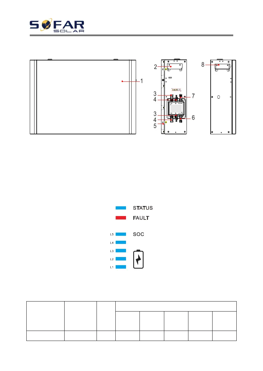
Battery module port:
Figure.2-4 Battery module port diagram
1 Battery module 2 Left side handle 3 Output terminal B+
4 Output terminal B- 5 Grounding hole 6 Communication output ( Link Port Out )
7 Communication input(Link Port In) 8 Right side handle
2.4.
Indicator lights description
Figure.2-5 Indicator diagram
Normal status indicator light:
Table 2-1. Normal status indicator light definition
 Loading...