BTS E5~20-DS5 user manualV1.1
Copyright © Shenzhen SOFARSOLAR Co., Ltd
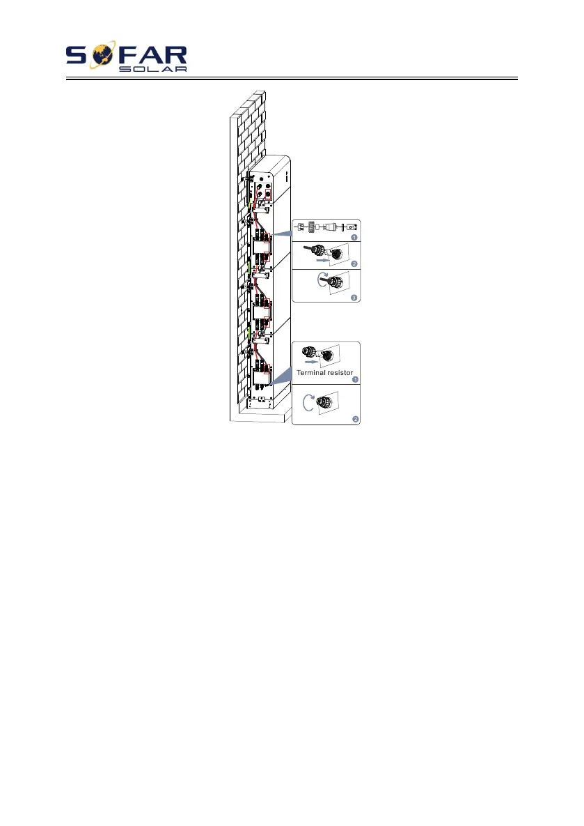
Figure. 4-4 Diagram of internal signal cable connection
Note:
For the safety of the battery system with a single cluster capacity of
20kWh, a base installation package is recommended and divided into two
columns for installation. The following points should be paid attention to
during electrical connection:
1) Connect the power cable. Connect the upper expansion terminal
(B+,B-) on the uppermost battery module in one column (without the
DBU) to the lower expansion terminal (B+,B-) on the bottom battery
module in the other column.
2) For communications cable connections, connect the Link Port In on
the uppermost battery module in one column (without the BDU) to
the Link Port Out on the bottom battery module in the other column.
 Loading...