Setting up the reader
10
Grounding and
Shielding
Single RM Reader
When connecting a single RM reader to the reader bus, use twisted pair, shielded
minimum 24 AWG cable. Attach the shield at the controller end.
(Refer to TAB 2010-15 “RM Reader ESD Protection Guidelines.”)
Attach a local earth ground (18 or 22 gauge) wire to the J5 component on the RM
reader.
Multiple RM Bus Devices
When wiring an RM reader to a bus with multiple devices, such as other RM-4s, I/8s, or
R/8s:
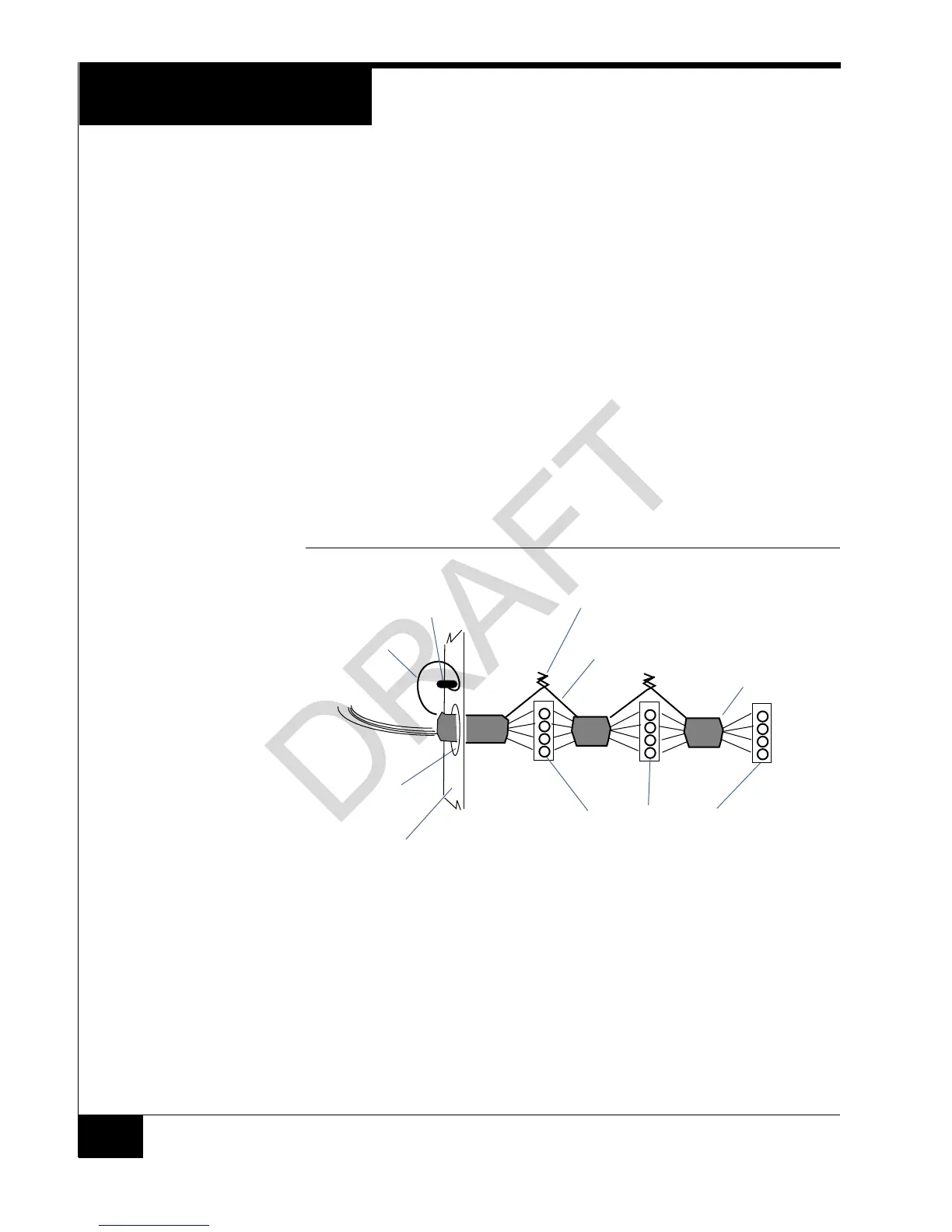
Attach the shields along the bus together (insulate each connection). Snip off the
shield wire at the end of the bus, see Figure 6.
Attach the shield to the ground at only one point – at the ground stud inside the
controller
Attach a local earth ground (18 or 22 gauge) wire to the J5 component on the RM
reader.
FIGURE 6. Reader Shield Wiring
Setting Module
Address and
EOL Termination
To set the module address, set SW1 (16 position rotary switch) to a number from one to
eight. Every reader on a bus must have a unique address.
To set RS-485 EOL (End of Line) termination, set SW3-5 to the On (closed) position if
the module is the last unit on the bus. If the module is not the last unit on the bus,
SW3-5 should be Off (open).
RS-485 connector on a reader
Knockout
Twist shield wires together and insulate
(do not ground)
Ground stud
(bus configuration)
Shield wire
Enclosure/cabinet
Shield wire
Snip off shield
wire at end of
bus
 Loading...