Setting up the reader
11
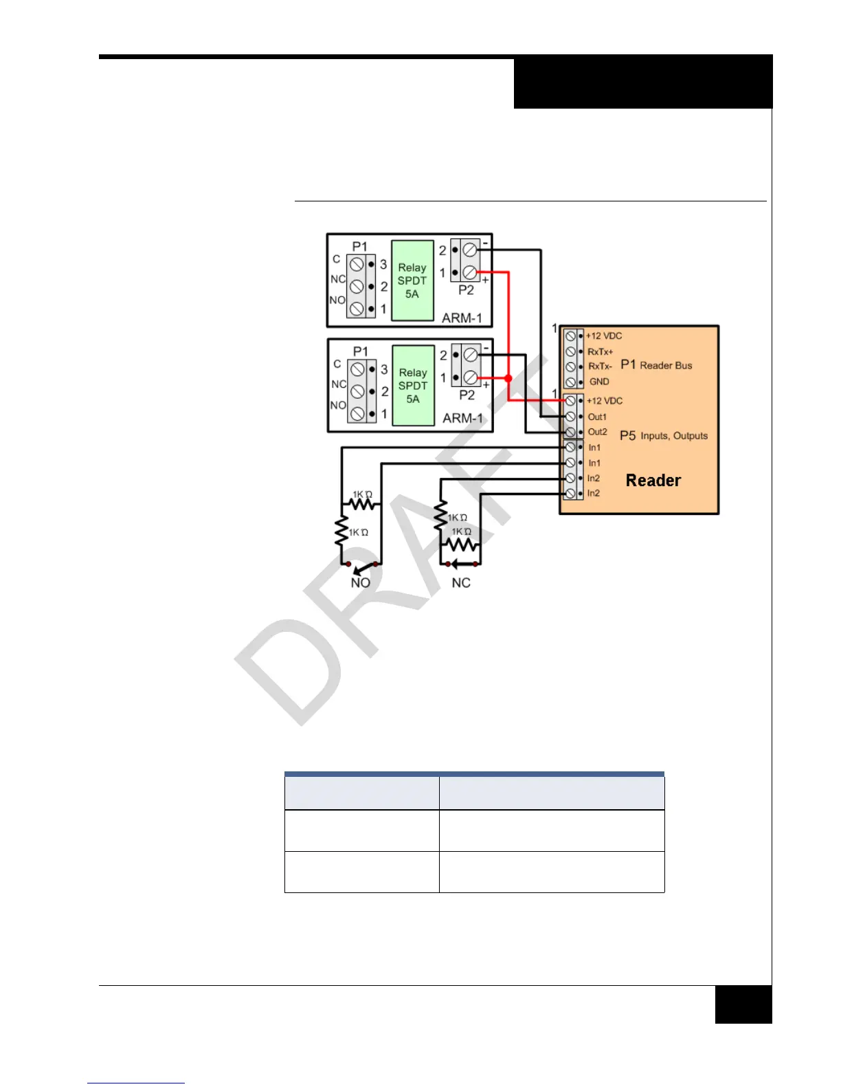
Figure 7 shows how to connect ARM-1 relay modules to the reader outputs and how to
wire NO (Normally Open) and NC (Normally Closed) supervised inputs.
FIGURE 7. Reader Input/Output Connections
Installing the ARM-1
Relay Module
Two ARM-1 relay components can be connected to the reader through the P5 connector
(Table 5 ).
RM P5-1 is the common (+12 VDC) pin for either ARM-1.
RM P5-2 is the output drive (GND) for the first relay.
RM P5-3 is the output drive (GND) for the second relay.
TABLE 5. ARM-1 Wiring
Module (131-192) Wiring
ARM-1 Relay ARM P2-1 to RM P5-1
ARM P2-2 to RM P5-2
ARM-2 Relay ARM P2-1 to RM P5-1
ARM P2-2 to RM P5-3
 Loading...