Setting up the reader
9
Wiring the Inputs,
Outputs, Reader Bus
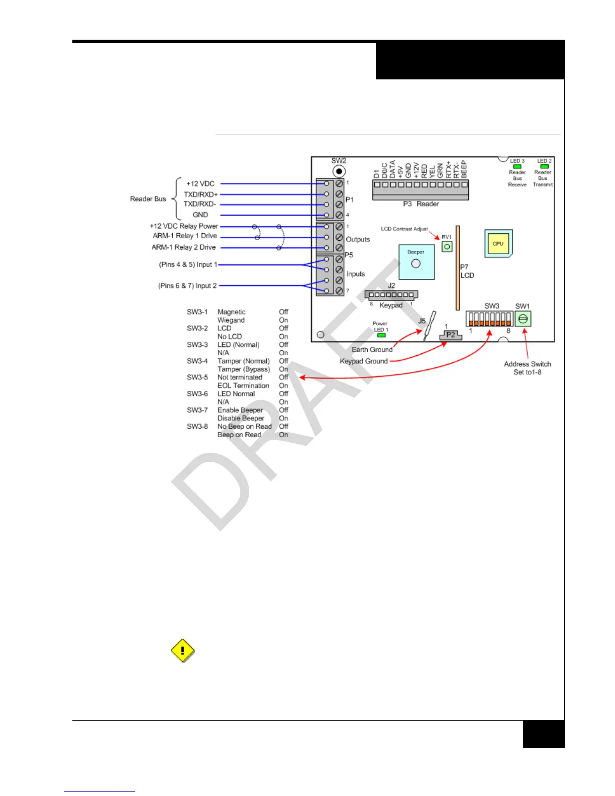
Figure 5 shows RM-4 P1 and P5 wiring.
FIGURE 5. RM-4 Wiring Requirements
NOTES SW3-7 and SW3-8 refer to the Beeper on the RM-4.
P3 BEEP refers to the Beeper on the read head, if it exists. There is no Beeper on the
reader read heads. Some third-party readers that are connected to a standalone reader
have beepers.
SETTING UP THE
READER
To Set Up the Reader:
1. Set the Reader Address Switch, SW1 (a 16 position rotary switch, see Figure 5), to a
number from one to eight. Each Reader along the bus must have a unique address.
2. The SW3-1, SW3-2, SW3-3, and SW3-6 Configuration Switches are factory preset
for the readers, as shown in Figure 5 on page 9.
3. Note that you can override SW3-4, SW3-5, SW3-7 and SW3-8 if desired.
To properly terminate an RS-485 line, only the last unit on the bus should have
SW3-5 in the On (closed) position.
 Loading...