Do you have a question about the Sokkia im-101 and is the answer not in the manual?
Procedures and guidelines for charging the instrument's battery.
Precautions and guidelines for using Bluetooth and Wireless LAN functions.
Guidelines to maintain the instrument's water and dust resistance specifications.
Specific operational advice for using the instrument in very cold conditions.
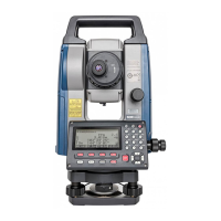
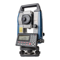
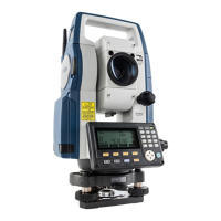
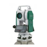
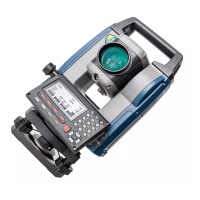
Identifies and describes the various physical components of the instrument.
Explains the different operational modes and navigation flow of the instrument.
Details the use and precautions for wireless communication features.
Explains fundamental key presses and softkey functions for instrument operation.
Describes the various screens and information displayed by the instrument.
Details the Starkey mode for quick access to common measurement settings.
Step-by-step procedure for charging the instrument's battery.
Instructions for safely installing and removing the instrument's battery.
Step-by-step guide on how to position the instrument over a survey point.
Instructions for leveling the instrument using circular and electronic levels.
Configuration steps for establishing Bluetooth communication with external devices.
Procedures for connecting the instrument to external devices using an RS232C cable.
Detailed procedure for accurately sighting a target using the instrument's telescope.
How to measure horizontal angles between points and set the zero direction.
Procedures for setting a specific horizontal angle or holding the current angle.
Explains how to perform angle measurements and output the data to a computer.
Procedure for measuring both distance and angle simultaneously.
Steps to measure distance and transfer the data to an external device.
How to measure coordinates and output them to a computer or peripheral.
Method for measuring the height of inaccessible points using Remote Measurement.
Setting instrument location, height, and backsight azimuth for coordinate calculations.
Determining instrument station coordinates by measuring known points.
How to set out points based on predefined coordinates using angle and distance.
Procedure for setting out points based on horizontal angle and distance from a baseline.
Method for setting out points at inaccessible heights using REM.
Steps to define a baseline by inputting or observing two points.
How to find required point coordinates by inputting length and offset from a baseline.
Procedure to measure point's horizontal distance from baseline and vertical distance from line.
Methods to define an arc by inputting parameters or observing points.
How to set out points along a defined arc using length and offset.
Steps to define a baseline for projecting points onto it.
Procedures for projecting points onto a defined baseline and calculating distances.
Configuration options for topography observation, including patterns and registration.
Procedure for conducting topography observations in R and L directions.
Measuring distance and angle to a target point using an offset point.
Finding target direction using included angle from offset points.
Measuring distances between target and two offset points for offset calculation.
Finding distance and coordinate of a plane edge where direct measurement is not possible.
Measuring distance and coordinates of a column's center using circumscription points.
Measuring slope, horizontal distance, and angle between points without moving instrument.
How to change the last measured point to the next starting position for missing line measurement.
Calculates various intersection types like 1 pt, Angle, 4-point, 2 Circles.
Determines point coordinates using azimuth and distance from a specified point.
Calculates target coordinates using instrument station, backsight, angle, and distance.
Calculates the intersection of two straight lines defined by four points.
Calculates intersections of two circles defined by center points and radii.
Calculates coordinates of a point extending along a defined line beyond an endpoint.
Divides a line segment into user-specified segments and calculates coordinates.
Calculates coordinates for points spaced at a designated pitch along a line.
Finds intersection points between two reference points using length or azimuth angle.
Sets the instrument station as the reference point for route surveying.
Calculates center and width pegs for a straight line using reference and IP point coordinates.
Finds center and width pegs for a circular curve using BC and IP point coordinates.
Calculates center and width pegs for a spiral (clothoid) curve.
Calculates center and width pegs for a parabola curve.
Finds coordinates of cardinal points, centerline, and width pegs from 3 IP points.
Calculates intersection angle, curve properties, and peg coordinates from IP points.
Finds center and width pegs for a route containing multiple curves.
Procedures for inputting intersection points (IPs) to define route curves.
Setting parameters like radius, offset, and lengths for route curves.
Automatically calculates cardinal points and pegs based on curve properties.
Finds coordinates of arbitrary points on a calculated curve.
Finds route widths and coordinates using inverse width peg calculation.
Presets curve type and BP point for subsequent calculations.
Measures and sets out points along a cross-section of a road or linear feature.
Stores instrument station coordinates, height, and other details in the current JOB.
Stores backsight station data and allows azimuth angle setting.
Records angle measurement values, including target height, point name, and code.
Stores distance measurement results, including target height, point name, and code.
Records coordinate measurement results, including target height, point name, and code.
Stores both distance and coordinate data for the same point name.
Allows recording of text notes associated with measurements.
Displays recorded data within the current JOB, searchable by point name.
Procedures for deleting recorded measurement data from the current JOB.
How to select the current JOB and the Coordinate Search JOB, and set scale factor.
Procedures for clearing data within a designated JOB.
Methods to register or delete coordinate data for known points.
Procedures for saving, entering, or deleting codes used for observation data.
Displays the list of registered codes.
Steps to output measurement results, station data, and notes to a host computer.
Instructions for physically inserting a USB flash drive into the instrument.
Procedure for saving measurement data from a JOB to a USB flash drive.
How to load known point data or codes from a USB flash drive into the iM.
Viewing file information, editing names, and deleting files on the USB drive.
Steps to format the USB flash drive using the instrument.
Settings for angle and tilt measurements, including compensation and correction.
Settings related to distance measurement modes, units, and corrections.
Configuration for different target types (prism, sheet) and prism constant.
Settings for atmospheric conditions affecting measurements, including correction factors.
Power management settings like auto-off, resume function, and EDM eco mode.
Settings for instrument display, contrast, guide light, and volume.
Customizing softkey assignments for efficient instrument operation.
Procedures to reset instrument settings to factory defaults or initialize data.
Checking and adjusting the circular level for accurate instrument setup.
Checking and adjusting the tilt sensor for accurate angle measurements.
Measuring and correcting collimation errors for accurate observations.
Checking and adjusting the optical plummet for precise centering.
Checking and ensuring the additive distance constant is accurate.
Checking and adjusting the laser plummet for accurate centering.
Procedure to eliminate vertical circle zero index inaccuracy by measuring with both faces.
Explains how the instrument corrects for atmospheric refraction and earth curvature in distance calculations.
| Brand | Sokkia |
|---|---|
| Model | im-101 |
| Category | Measuring Instruments |
| Language | English |