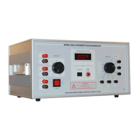
The Solar Model 9354-2 Transient Generator is an instruction manual for a transient generator used in electromagnetic compatibility (EMC) testing. It provides nine front panel selectable output waveforms, including six damped sinusoidal pulses (10 KHz, 100 KHz, 1 MHz, 10 MHz, 30 MHz, and 100 MHz) and three double exponential pulses (6.4 µS, 70 µS, 120 µS).
Function Description
The device generates various transient pulses for conducted susceptibility or vulnerability testing of subsystems and equipment. It can be used for direct injection between an isolated equipment case and ground, or from a connector pin to the connector shell. It also supports indirect injection using inductive coupling devices like the Type 9335-2 Multi-port Coupling Device or other injection probes for system susceptibility testing on interconnecting cables. The generator's output can be isolated through a Solar Type 9335-2 coupling device, and for 6.4 µS, an audio isolation transformer Solar Type 6220-4 can be used.
Important Technical Specifications
The Model 9354-2 provides a wide range of output voltages and impedances depending on the selected waveform.
Damped Sinusoidal Waveforms:
- 10 KHz: Open Circuit Voltage: 30.0 V, Source Impedance: < 0.25 Ω
- 100 KHz: Open Circuit Voltage: 300.0 V, Source Impedance: < 3.8 Ω
- 1 MHz: Open Circuit Voltage: 3200.0 V, Source Impedance: < 28.0 Ω
- 10 MHz: Open Circuit Voltage: 3200.0 V, Source Impedance: < 39.0 Ω
- 30 MHz: Open Circuit Voltage: 1500.0 V, Source Impedance: < 50.0 Ω
- 100 MHz: Open Circuit Voltage: 600.0 V, Source Impedance: < 50.0 Ω
Double Exponential Waveforms:
- 6.4 µS: Rise Time: 100 nS, Open Circuit Voltage: 1600 V, Source Impedance: < 2.0 Ω
- 70.0 µS: Rise Time: 6.4 µS, Open Circuit Voltage: 1600 V, Source Impedance: < 2.0 Ω
- 120.0 µS: Rise Time: 40 µS, Open Circuit Voltage: 750 V, Source Impedance: 1.0 Ω
The six damped sinusoidal waveforms meet the requirements of MIL-STD-461E and MIL-STD-461D, test method CS116. Two of these (1 MHz and 10 MHz) have extended limits to an open circuit voltage of 3200 volts peak to meet DO-160D, Section 22, Table 22-2 requirements. The double exponential pulses are designed to meet DO-160C, Section 22 requirements.
Power Requirements:
- Power Source: 115 V unit: 60 Hz, or 230 V unit: 50 Hz
- Power Consumption: 50 Watts
- Power Line Fuses: 115 V unit: 2 @ 3A Slow-Blow, or 230 V unit: 2 @ 1.5A Slow-Blow
Physical Characteristics:
- Net Weight: 55 Lbs. (25 Kg)
- Shipping Weight: 58 Lbs. (26.3 Kg)
- Height: 9.12 In. (222 mm)
- Width: 17.12 In. (435 mm)
- Depth: 13.50 In. (343 mm)
Usage Features
- Panel Mounted Digital Voltmeter: Displays the reference open circuit discharge voltage.
- Trigger Modes: Automatic or manual trigger for damped sinusoidal pulses. Manual triggering for double exponential pulses.
- Automatic Mode: Multiple pulses for damped sinusoidal waveforms and external modules are set internally at one pulse per second. This mode is not provided for the 6.4, 70, or 120 µS double exponential pulses.
- Manual Mode: A front panel push button provides manual triggering for all nine waveforms, including external modules.
- Variable Peak Output Voltage: Adjustable from the front panel as a percentage of the charged circuit voltage. The voltmeter display is a reference for an open circuit voltage.
- Polarity Reversal: For damped sinusoidal waveforms, reversing the cable direction through the window reverses the pulse polarity. For double exponential waveforms, the terminal (banana) jacks can be reversed.
- Output Impedance Manipulation: While the generator has unique output impedances for each waveform, they can be manipulated with resistive networks or optimized through the selective windings of the Type 9335-2 Multi-port Cable Coupling Device to achieve desired results (e.g., increased voltage, lower current, or impedance matching).
- High Energy Outputs: All output BNC connectors and binding posts allow connection to coupling devices for series cable injection of up to 3200 volts peak unloaded and 1600 amperes peak loaded. The connectors are insulated for open circuit voltages greater than 4500 volts peak and short circuit currents exceeding 2250 amperes peak.
Maintenance Features
- Independent Waveform Circuits: An independent circuit for each waveform improves reliability and simplifies maintenance.
- Solid State Switching: Solid state switching and RC networks across coils, switches, and relay contacts reduce arcing, eliminate contact bounce, and increase component life.
- Capacitor Discharge: Turning off the power switch slowly discharges the main pulse storage capacitors. Pulsing in the 120 µS long wave position discharges the capacitors faster.
- Safety Precaution: To extend the generator's life, keep its amplitude below 87% except when actively testing, and turn it down as soon as testing is complete. Before any maintenance or handling, turn the selector switch to 120 µS, turn the amplitude knob to zero, and pulse the 120 µS to discharge all capacitors.
Optional Accessories
- Type 6220-4 High Voltage Transformer: 2:1 step-down injection transformer for doubling current (voltage reduced to ~50%).
- Type 9335-2 Universal Coupling Device: Frequency range 10 kHz to 10 MHz, providing various voltage and current transfer ratios and impedance ratios (e.g., 1:1, 2:1, 1:1.5, 1:3).
- Type 9410-1 High Voltage Attenuator: 40 dB 50/50 ohm attenuator for oscilloscope protection.
- Type 9454-1 High Voltage Attenuator: 40 dB 600/50 ohm attenuator for simulating open circuit and oscilloscope protection.
- Type 9142-1N Injection Probe: For injecting 1 MHz to 100 MHz damped sine waves.
- Type 9616-2 High Voltage Surge 70 µS.