Solar Electronics Company
2. DESCRIPTION
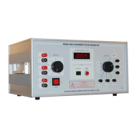
1 The Model 9354-2 Transient Generator provides nine front panel selectable output
waveforms, including six damped sinusoidal pulses (10 KHz, 100 KHz, 1 MHz, 10 MHz,
30 MHz, and 100 MHz) and three double exponential pulses (6.4 μS, 70 μS, 120 μS).
2 Modes of Operation - The Model 9354-2 has three modes of operation. A front panel
switch selects either AUTO / MANUAL single pulse. The waveform selector switch also
selects ACCESSORY OUTPUT for the external modules (See 9554- ( ) manual for more
details on Variable Frequency Modules )
A. Automatic Mode - Multiple pulses for the damped sinusoidal pulses well as for the external
modules are set internally at the factory for one pulse per second. The pulse rate can be verified
using a counter or Analog Oscilloscope. Monitor the 10 kHz output. Set scope to .2s per/div and 2v
per/div using a standard 10X scope probe you will be able to see a pulse on every 5
th
division. Automatic
triggering is not provided for the 6.4, 70, or 120 μS double exponential pulses,. The double
exponential pulses are triggered by the manual push-button only.
B. Manual Mode - A push button on the front panel provides manual triggering for all nine
waveforms Including the Type 9554-( ) modules through the connecting cable.
3 Peak amplitude of the selected output pulse is adjustable from the front panel as a
percentage of the charged circuit voltage. The front panel digital voltmeter displays open
circuit discharge voltage. The 40 dB high voltage attenuator Type 9454-1 is used to
protect the oscilloscope. (Note: scope probes do not provide proper attenuation or coupling 50
ohm to the oscilloscope).
4 Polarity - The six damped sinusoidal waveforms outputs use BNC connectors, by
reversing the direction of the cable through the window will reverse the polarity of the
pulse, while the three double exponential waveform use terminal (banana) jacks can be
reversed. The application of the type 6220-4 transformer coupling device and the ability
to isolate the pulse from EUT ground is ideal for isolated case injection.
5 Output impedances are unique: Although the Model 9354-2 Transient Generator's
open circuit voltages, and output impedances are unique for each selected waveform,
they can be manipulated with resistive networks (see par 9.0) the energy transfer can also
in most cases be optimized through the different selective windings of the Type 9335-2
Multi-port Cable Coupling Device. The unique winding arrangement of this coupling
device provides a selection of step-up or step-down impedance ratios with respect to the
transient generator source impedance and coupled load impedance. This can provides a
better impedance match or power transfer, and higher open circuit voltages into the
cable bundle passing through the window of the device. It is the Engineers discretion to
select the proper port or resistive network to accomplish the desired result (increase
voltage, lower current or to increase current and lower voltage) or to simply match the
impedance of the injection probe port to the output impedance or the selected waveform.
(Note: Frequency range of the Type 9335-2 is 10 kHz to 10 MHz).