22
23
4. Installation 4. Installation
4.5 Cable Connection
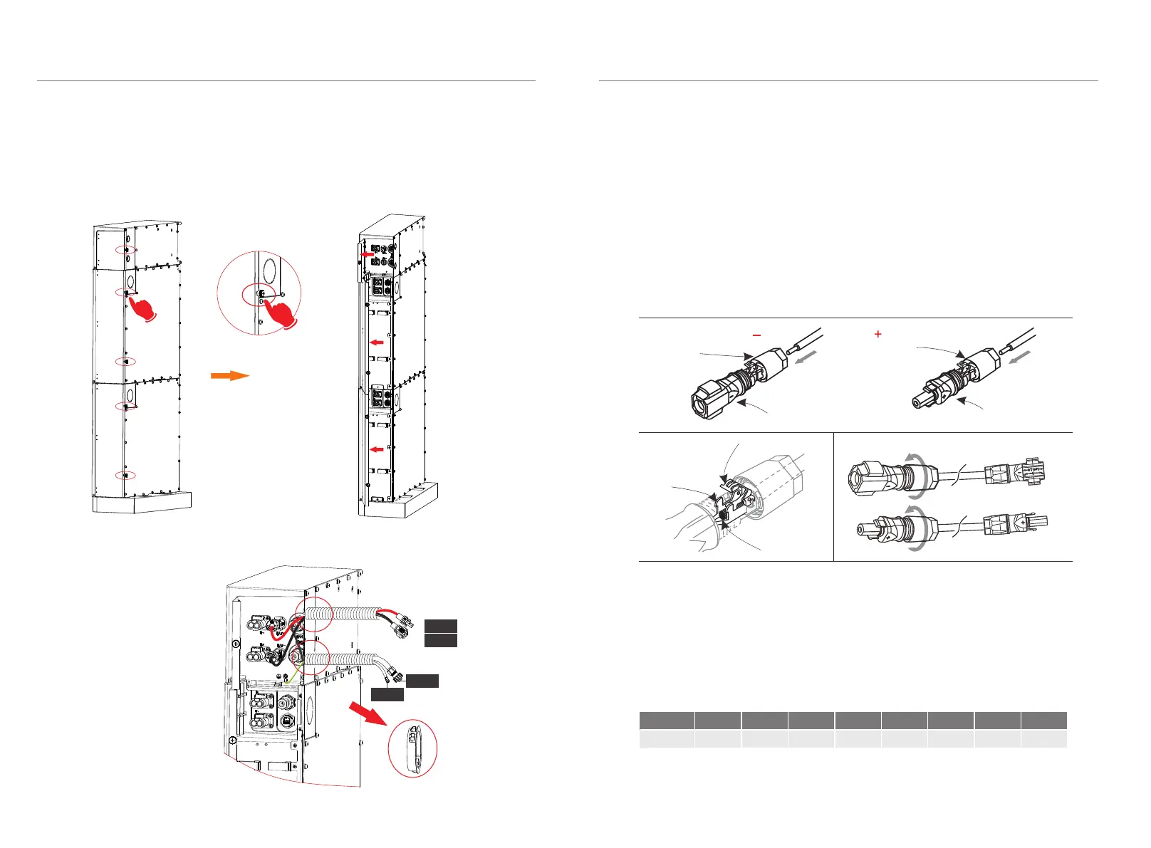
4.5.1 Connecting Cables to Inverter
Before connecting the cables, the right cover of the battery needs to be unscrewed
by hand
Cable Connection Steps:
Step2. Insert the stripped cable up to the stop (negative cable for DC plug(-) and
positive cable for DC socket(+) are live). Hold the housing on the screw
connection.
Step3. Press down the spring clamp until it clicks audibly into place (You should be
able to see the fine wie strands in the chamber)
Step1. Strip the cable(A/B:2m) to 15mm.
DC plug housing(-) DC socket housing(+)
screw connectionscrew connection
spring
chamber
wire strands
Step4. Tighten the screw connection(tightening torque:2.0±0.2Nm)
Step2.
Step3. Step 4.
Ø
The wire order of the communication cable is the same as theCAN
communication cable.
Connecting the CAN Communication Cable
It is required for the BMS to communicate with the inverter for proper operation.
Note that the CAN communication cable is shielded with steel tubes.
Ø
BMS to Inverter:
BAT+ to BAT+(A:2000mm),
BAT- to BAT- (B:2000mm),
CAN to CAN (D:2000mm)
Sequence
1 2 3 4 5 6 7 8
CAN
/
/
CAN_H
CAN_L
/
A1
B1
GND
+
-
To Inverter
BAT-
BAT+
GND
CAN