26
27
4. Installation
+
-
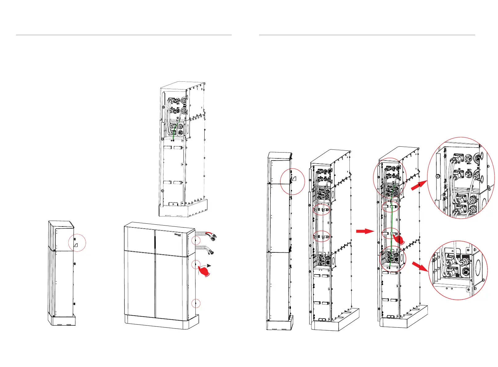
Ensure that both ends of the cables are connected to the correct connector,
which are on the right side of the BMS and battery module.
4.5.4 Connecting Cables to attery ModulesB
For two battery modules:
BMS to Slave1: B+ to B+ (C:120mm); COMM to COM1 (E:200mm)
BMS to Slave2: B- to B- (A1:690mm)
Slave1 to Slave2: B- to B+ (A1:690mm); COM2 to COM1 (B1:600mm)
Install a fixed wall bracket on the battery module, and thencheck to make
sure the connections are securely locked.
Ø
4. Installation
BMS to Slave1:
B+ to B+ (C:1200mm),
B- to B- (A1:690mm),
COMM to COM1 (E:200mm)
Slave1
Slave2
BMS
The BMS and battery module need to be grounded.
The BMS and battery modules need to be grounded.
Between battery modules need to be grounded.