5. Equipment Installation 5. Equipment Installation
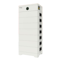
Sequence
1 2 3 4 5 6 7 8
BMS
/
/
BMS_H
BMS_L
/
A1
B1
GND
■ Making a BMS communication cable
If users want to make a BMS communication cable or a BMS communication cable
is required to be made before wiring, to ensure normal operation of BMS and
inverter, please read the following carefully.
The specific definition of the communication cable is shown as follows:
The wire order of the communication cable is as follows:
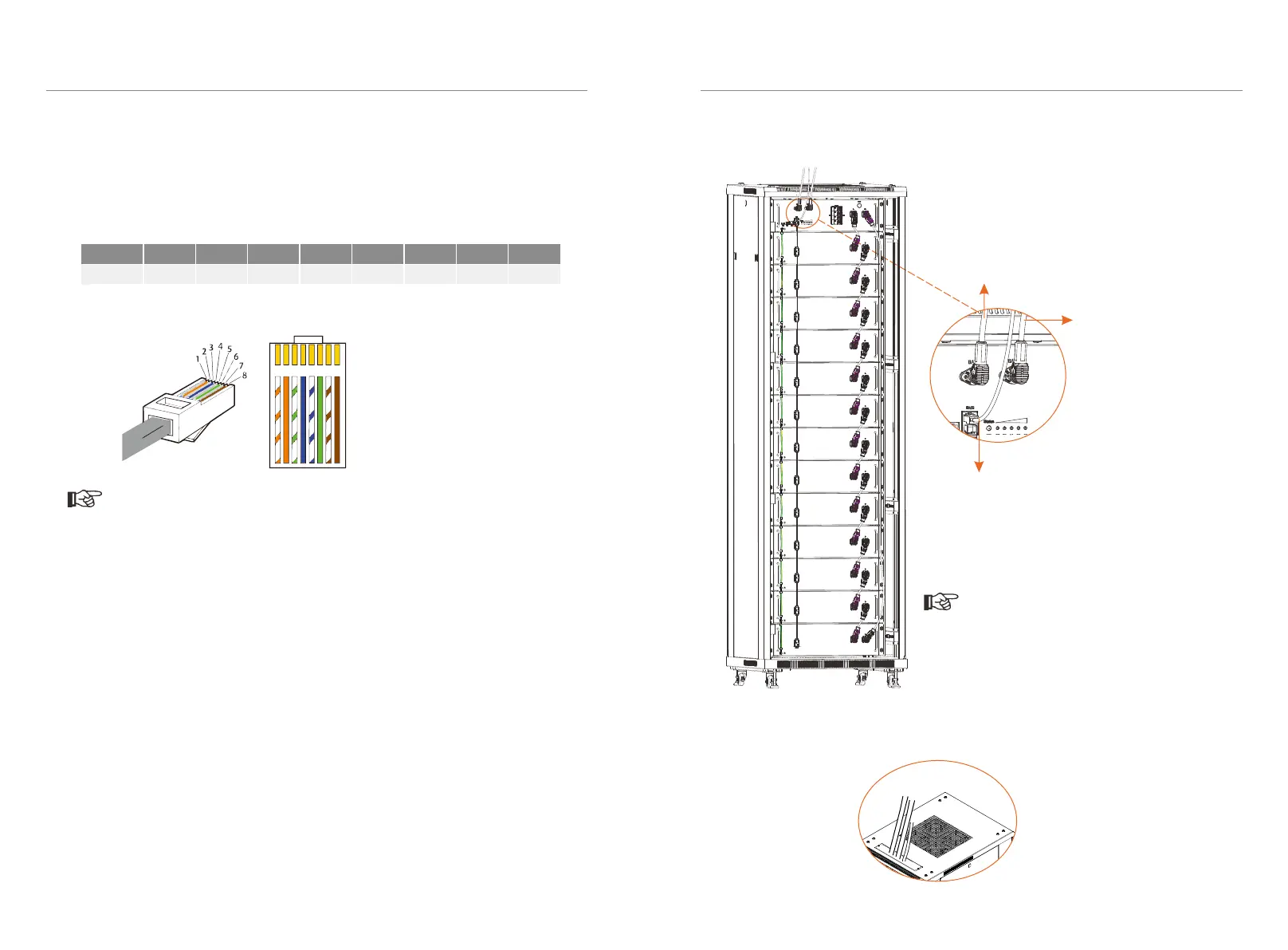
Connect cables between BMS and inverter. See figure below.
After completing wiring, these cable shall be through the threading hole on the
caber plank.
Front
Rear
Cables
42
43
As users insert a power cable, the users
should hear a click which indicates that the
cable connector is properly inserted into
the port.
Note!
Communication cable: connect
BMS of BMS (battery management
system) to BMS of inverter
(Note: The Link port on the BMS is
for parallel connection only. DO
NOT use for any other purposes.)
Power cable: connect BAT+
of BMS to BAT+ of inverter
Power cable:
connect BAT- of BMS
to BAT- of inverter
The BMS communication cable shall have a shield layer.
Note!
1 2
3
4
5
6 7 8
1) Orange stripes on white
2) Orange
3) Green stripes on white
4) Blue
5) Blue stripes on white
6) Green
7) Brown stripes on white
8) Brown
 Loading...