6. Commissioning
6 Commissioning
6.1
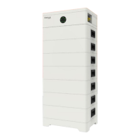
DIP Switch
The DIP switch 4 is pressed at the factory settings.
Note!
To adjust the DIP switch, a small flat-head screwdriver shall be prepared by users
themselves.
The following figure is DIP switch, and it is equipped on BMS.
6. Commissioning
6.2
Commissioning
Before commissioning, please check to ensure that, the installed battery modules
are the same model battery module, and all the ground wires, power cables and
communication cables are connected.
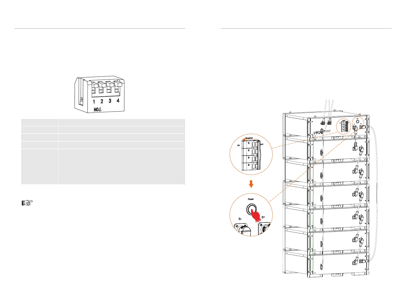
■ Power ON
After finishing wiring,
1. Turn the Breaker on;
2. Press the POWER buttom for 5 sec, to start system. See figure below.
44
45
Description
DIP switch 1 A reserved function
DIP switch 2 A reserved function
DIP switch 3 A reserved function
DIP switch 4
Terminal resistance
Note: 1. The DIP switch 4 shall be flipped down (open the
circuit) when connecting BMS to inverter; 2. In case of parallel
connection, only shall the DIP switch 4 on the last BMS be
flipped down (open the circuit), and the DIP switch 4 on the rest
of BMS shall be flipped up (close the circuit).
 Loading...