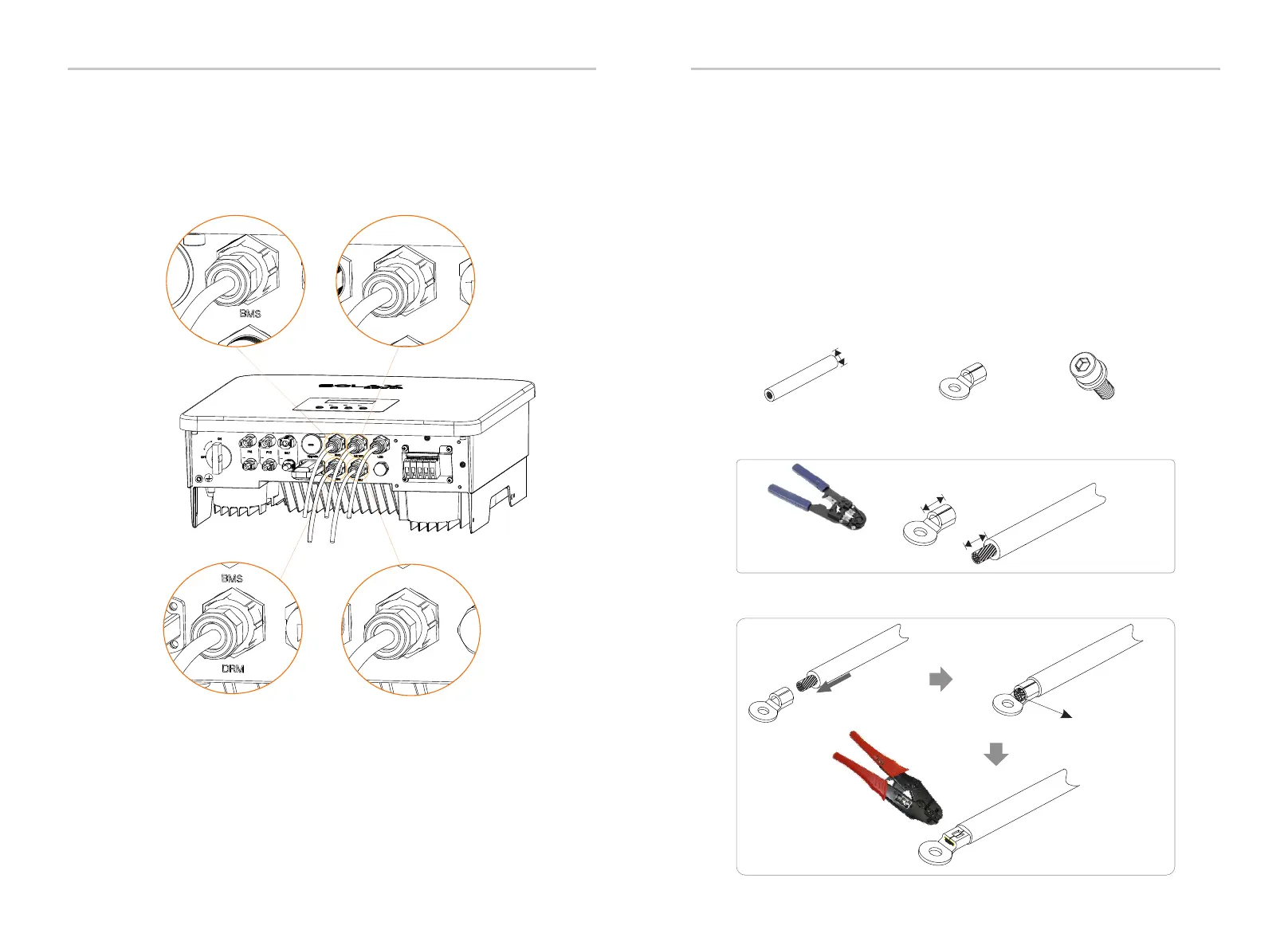
The user must make two ground connections :one shell grounding, and one
equipotential grounding .This prevents electric shock.
Ground connection steps:
Ø
Step 2. Strip the grounding cable insulation(lenhth”L2), insert the
stripped cable into the ring terminal, and then clamp it.
C
Step 1. Prepare a one-core cable (12AWG), and then find the ground
terminal in the accessories.
One-core cable (12 AWG)
OT terminal
L1
12AWG
L2=L1+3mm
Diagonal pliers
Step 3. Insert the stripped cable into OT terminal and tighten the terminal
with a terminal crimping tool.
Leaking cable
Hexagon socket screws
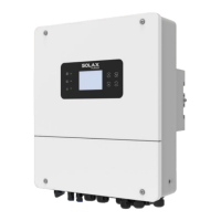
Step 5: Finally, find the corresponding COM, METER, CT, DRM poets on the
inverter and insert the communication cable into the corresponding ports.
Note: If the PV end of the inverter is not connected with earth , the inverter
will turn on a red light Inspect and report ISO Fault .This inverter complies
with IEC 62109-2 clause 13.9 for earth fault alarm monitoring.
The ground wire port of X1-Hybrid G4 M series inverter has been
connected, and the D series needs to be wired according to the
following steps.
Crimping Tool
58
59
Meter/CT
Meter/CT
COM/LCD
Electrical Connection
Electrical Connection
5.6 Grounding Connection (mandatory)
 Loading...