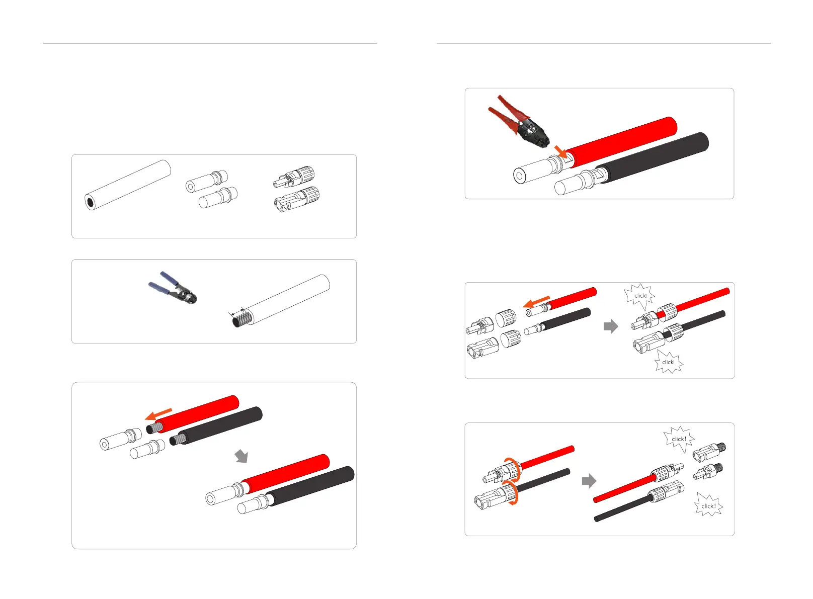
Crimping Tool
Positive terminal
Negative terminal
Electrical Connections
Electrical Connections
7
mm
Step 1. Turn off the DC switch, connect the PV module, prepare a 4 mm PV
cable, and find the PV (+) terminal and PV (-) terminal in the package.
Step 2. Use a wire stripper to strip the 7 mm insulation layer of the wire end.
Wire stripper
Figure 1
Figure 2
Ø Connection step
PV cable
PV pin
Negative terminal
Positive terminal
Positive PV pin
Negative PV pin
Positive metal terminal
Negative metal terminal
36 37
Step 3. Tighten the cable with the insulation layer stripped and insert it into
the metal terminal (see Figure 1), make sure all wires are inserted into the
metal terminal (see Figure 2).
The PV port wiring of M-series inverter has been completed, and it
can be used directly with the PV port of the X1-Matebox. The D series
needs to be wired according to the following steps.
Step 5. The PV joint is divided into 2 parts - the plug and the fastening
head. Insert the cable through the fastening head and the opposite plug.
Notice that the red and black lines correspond to different of plugs. Finally,
force the cable pair into the plug, will a "click" sound, which indicates that
the connection is completed.
Step 6. Tighten the fastening head and insert into the
corresponding positive and negative (PV+/PV-) ports of the inverter.
Step 4. Tighten the PV pin contact and the wiring harness to make the
connection tight without looseness.
PV+
PV-
Negative
Positive

 Loading...