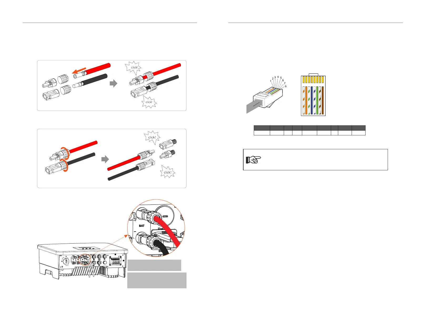
BMS port definition
1 2
3
4
5
6 7 8
1) White with orange stripes
2) Orange
3) White with green stripes
4) Blue
5) White with blue stripes
6) Green
7) White with brown stripes
8) Brown
Ø Communication connection
BMS_CANH
GNDBAT_TEMP GND
BMS_CANL
2
3 4
5
6 7 81
PIN
X BMS_485A BMS_485B
Electrical Connection
Electrical Connection
Definition
50
51
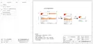
Step 7. Insert the battery power lines into the corresponding BAT port (+), (-)
of the inverter.
The communication interface between the inverter and the battery uses
the waterproof connector with RJ45.
Notice!
After the BMS communication between the battery and
the inverter is finished, the battery will work normally.
BAT+
BAT-
Negative
Positive
Positive terminal
Negative terminal
Step 5. The BAT joint is divided into 2 parts - the plug and the fastening
head. Insert the cable through the fastening head and the opposite plug.
Notice that the red and black lines correspond to different of plugs. Finally,
force the cable pair into the plug, will a "click" sound, which indicates that
the connection is completed.
Step 6. Tighten the fastening head and insert into the
corresponding positive and negative (BAT-/BAT+) ports of the inverter.
Note: The positive and negative
wires of the battery are not
allowed to be reversed!
Note: BAT port (Blue one)
not PV port(Black one)

 Loading...