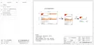
Ø CT Connection
CT connection diagram
Notice for CT connection:
LCD settings
>Select
CT
CT/Meter Setting
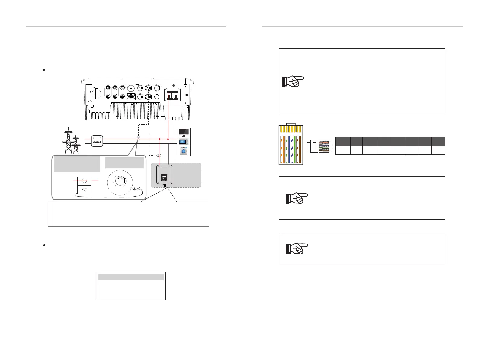
Electrical Connection
Electrical Connection
1 2
3
4
5
6 7 8
1
8
1
2 3 4 5 6 7 8
485A 485B X
CT1-2CT1-1
CT2-2
CT2-1
X
54
55
The current sensor measures the current on the live wire between the
inverter and the public grid.
To select CT, you need to enter Use setting, then enter CT/Meter Setting.
Notice!
Only one of the Meter and CT connections can be
selected. Meter cable goes to pin terminal 4 and 5;
CT cable goes to pin terminal 1 and 8; reserve CT
cable goes to pin terminal 3 and 6. If you need this
feature, please contact us for assistance.
Notice!
• Do not place the CT on the N wire or ground wire.
• Do not put CT on the N line and L line at the same time.
• Do not place the CT on the side where the arrow points to
the inverter.
• Do not place the CT on non-insulated wires.
• The cable length between CT and inverter should not
exceed 100 meters.
• After CT is connected, prevent the CT clip from falling off.
It is recommended to wrap the CT clip around in circles with
insulating tape.
Notice!
If two meters were to be connected in the system,
the communication cables of the meters should be
connected in parallel, i.e. 485A & 485A, 485B & 485B.
If the user has other power generation equipment (such as inverter) at home
and wants to monitor both, X1-Hybrid G4 inverter provides CT2
communication function to monitor the power generation equipment. For
more information, please contact us.
Public grid
electricity
Notice: The arrow on the CT
must point at the public
grid.
CT
Meter/CT port is at the
bottom of the inverter.
Meter/CT
Grid
Household Meter
Loads
L
N
Other power
generation
equipment
ON
OFF
PV 1
PV 2
BAT
BMS
CAN
DRM
Met er/CT
COM /LCD
CT 1
CT 2
Upg rade/ D ONGLE

 Loading...