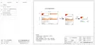
METER/CT pin is defined as follow:
1 2
3
4
5
6 7 8
Ø METER/CT communication cable
Electrical Connection
Electrical Connection
1
8
1
2 3 4 5 6 7 8
485A 485B X
CT1-2CT1-1
CT2-2
CT2-1
X
CAN
Meter/CT
COM/LCD
Distribution box
A
B
66
67
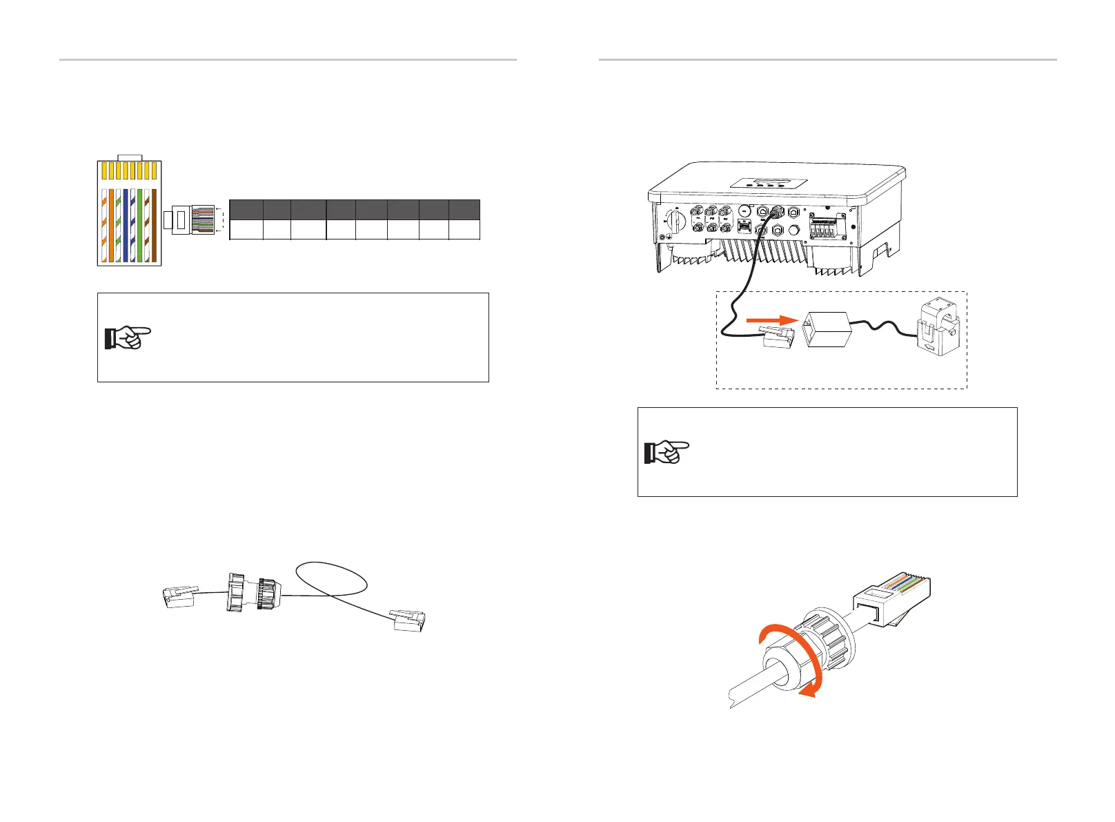
1) Users can customize the length of the CT communication cable. The
accessory package provides 1*RJ45 and 1*waterproof connector with RJ45
terminals.
When the CT cable is completed, connect the A terminal to the "CT/METER"
port of the inverter and tighten the waterproof screw, and connect the B
terminal to the RJ45 coupler.
Step 4. Tighten the completed Meter/CT/BMS communication line and
tighten the waterproof plug.
2) One side of the finished cable, Waterproof connector with RJ45 is
inserted into the inverter, and one side of the RJ45 terminal is inserted
into the CT connection.
U
p
g
r
a
d
e
/
D
o
n
g
l
e
Notice!
Only one of the Meter and CT connections can be selected.
Meter cable goes to pin terminal 4 and 5; CT cable goes to pin
terminal 1 and 8; CT2 cable goes to pin terminal 3 and 6.
Notice!
When installing, pay attention to water resistance. All the
connected parts of CT must be put into the distribution
cabinet.

 Loading...