09
08
Safety Safety
• 2.3 PE Connection and Leakage Current
• The inverter incorporates a certified internal Residual Current Device
(RCD) in order to protect against possible electrocution and fire hazard
in case of a malfunction in the cables or the inverter. There are two trip
thresholds for the RCD as required for certification (IEC 62109-2: 2011).
The default value for electrocution protection is 30 mA, and for slow
rising current is 300 mA.
• If an external RCD is required by local regulations, check which type of
RCD is required for relevant electric code. It recommends using a type-
A RCD. The recommended RCD values is 300 mA unless a lower value
is required by the specific local electric codes.
The device is intended to connect to a PV generator with a capacitance
limit of approx 700 nf.
• High leakage current!
• Earth connection is essential before connecting
power supply.
WARNING!
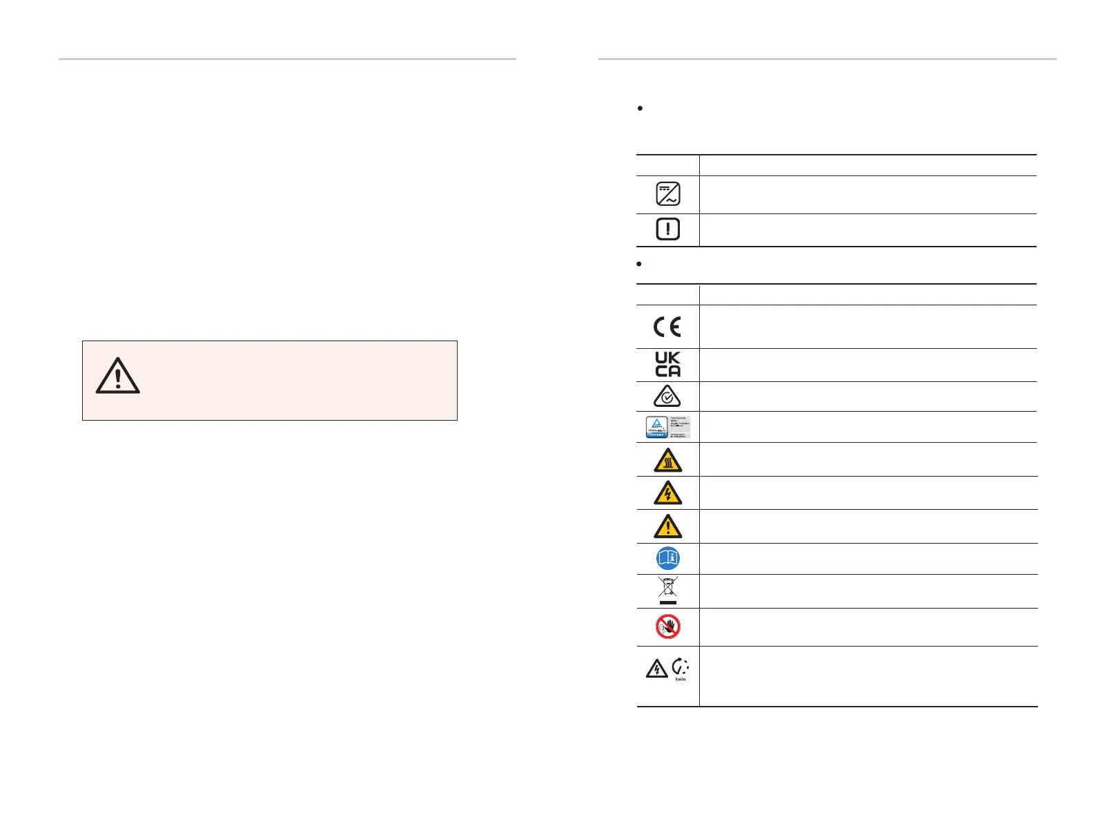
Symbol Explanation
When the blue light is on, it indicates the inverter is working normally.
When the red light is on, it indicates an error has occurred.
Symbols on the Type Label
Symbol Explanation
CE mark.
The inverter complies with the requirements of the applicable
CE guidelines.
RCM remark.
Beware of hot surface.
The inverter can become hot during operation. Avoid contact
during operation.
Danger of high voltages.
Danger to life due to high voltages in the inverter!
Danger.
Risk of electric shock!
Observe enclosed documentation.
The inverter can not be disposed together with the household waste.
Disposal information can be found in the enclosed documentation.
Do not operate this inverter until it is isolated from mains
and on-site PV generation suppliers.
TUV certification.
Compliant with UKCA standards.
Danger to life due to high voltage.
There is residual voltage in the inverter which needs 5 min to discharge.
• Wait 5 min before you open the upper lid or the DC lid.
2.4 Explanation of Symbols
Symbols on the Inverter
This section gives an explanation of all the symbols shown on the inverter
and on the type label.

 Loading...