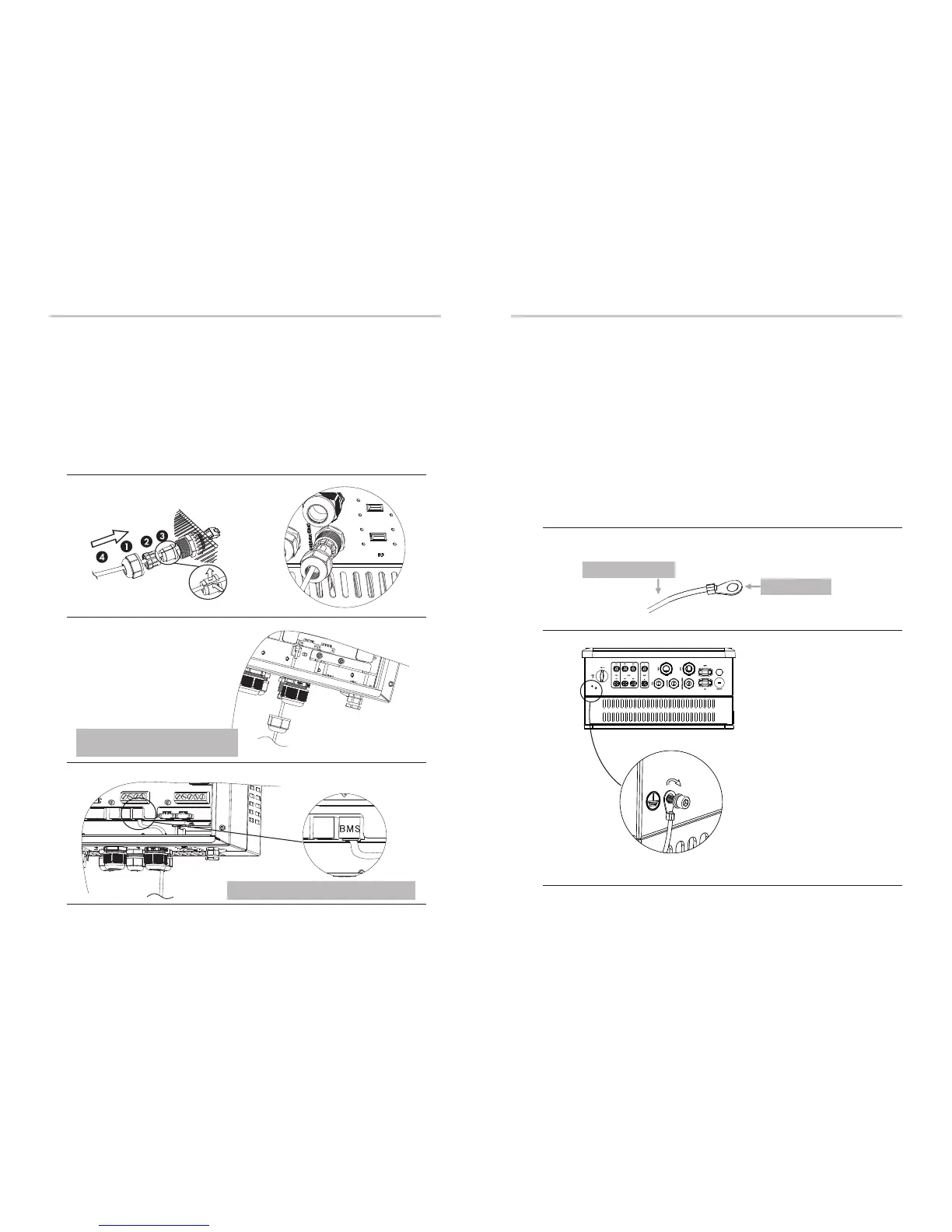
Communication Connection Steps:
Ø
Step3. Assemble the cable gland and screw the cable nut.
Step4. Insert one RJ45 side of the cable into BMS port inside of inverter and the
other side into RS485 or Can port of the battery.
Step1. Disassemble the GEN/Meter/BMS cable gland.
Step2. Prepare a communication cable(without sheath) and insert the commu-
nication cable through the cable nut.
Step1,2
Step3
Step4
6.5 Earth Connection(mandatory)
User can addtionally earth the inverter to the enclosure of a second earthing or
equipotential bonding if it is required by local safety. This prevents electric shock
if the original protective conductor fails.
Earth Connection Steps:
Ø
Step2. Place the ring terminal into the earthing rod and screw the earthing screw
tightly.
Step1. Strip the earthing cable insulation and insert the stripped cable into the
ring terminal, then clamp it .
Electrical ConnectionElectrical Connection
32
33
Cable size: 12AWG.
ring terminal
Step1
Step2
BMS Port: The first RJ45 port from right side
The seal is used for waterproof. Please
make sure it has been kept back.

 Loading...