Control Terminals – Option Boards
10
1010
10
RS-485 Communication ....................Terminals 23-24
Terminals: 23 (-), 24 (+) and terminal 22 (GND).
Optional RS485, half duplex with MODBUS
protocol, baud rate 1200, 2400, 4800, 9600 BPS.
Twisted shielded pair should be used and shield
connects to ground on the PLC/Computer side.
Terminals 4 & 5 must be wired to control supply
voltage for operation in communication mode (see
Communication Wiring Diagrams).
Profibus
9 pin D-sub connector is available for Profibus.
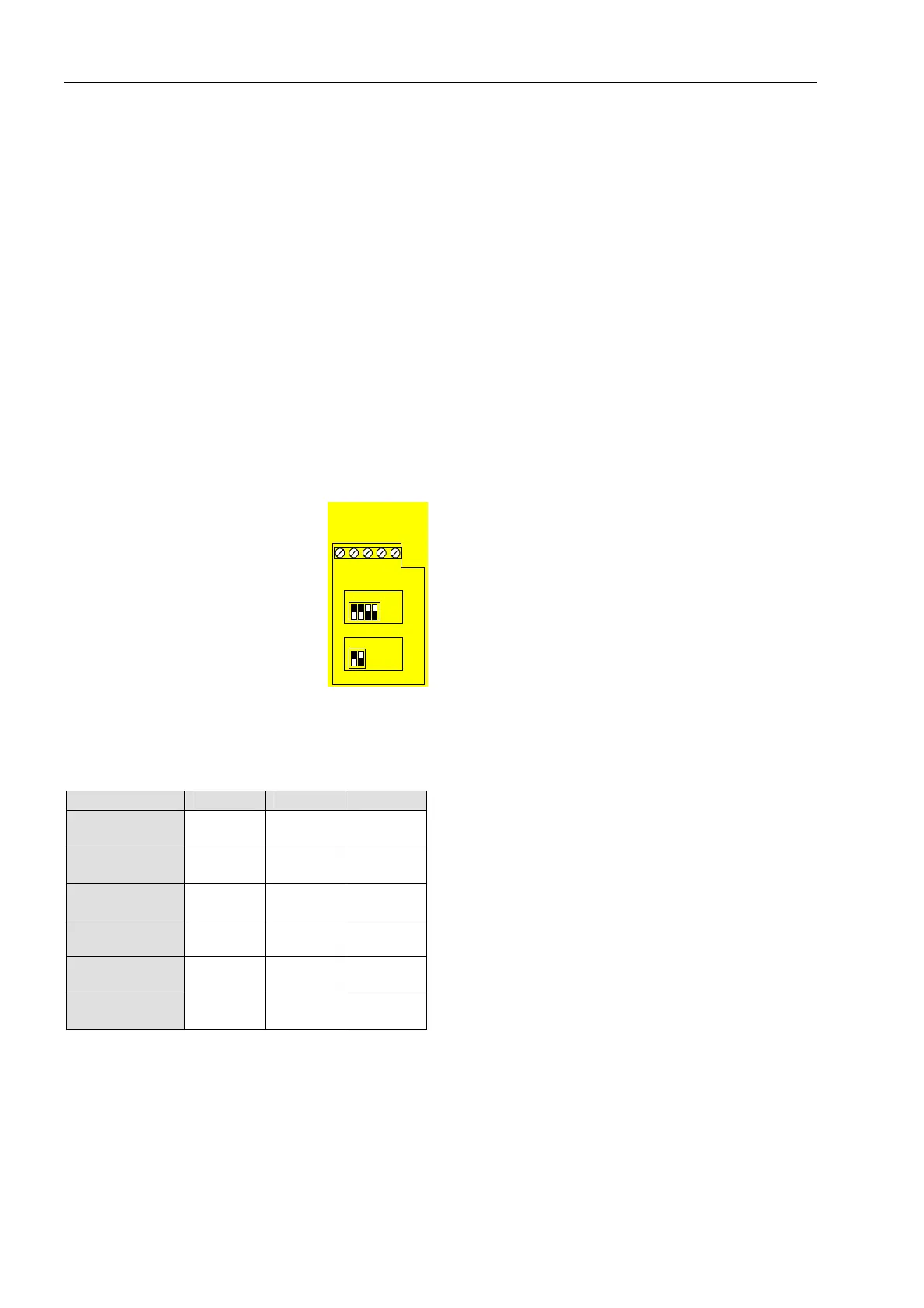
Analog I/O (option # 5) ....................Terminals 28-32
Terminals 28-29 leave open
Terminal 30 – Ground (leave oopen)
Terminal 31 – Analog output (-)
Terminal 32 – Analog output (+)
The Analog card output incorporates
two functions (Voltage & Current
outputs).
Dip switches allow selection
between:
0-10VDC, 0-20 mA and 4-20 mA
The Analog value is related to the
motor current and can be
programmed to normal or inverted
output. (Default = Normal)
Maximum value (20mA or 10Vdc) is
related to 2 x In.
Dip. Sw. S1
Dip. Sw. S2
(+) (-)
32 31 30
28
Dip switch No. 4-20 mA* 0-20 mA 0-10VDC
Dip-Switch S1
# 1
On On Off
Dip-Switch S1
# 2
On On Off
Dip-Switch S1
# 3
Off Off On
Dip-Switch S1
# 4
Off Off On
Dip-Switch S2
# 1
On Off Off
Dip-Switch S2
# 2
No use No use No use
* Default
Relays board
The board includes two relays that enable:
1) Operation and control of starter cabinet via
communication.
2) Up to speed relay, which energizes when By Pass
contactor is closed and current reduced below 115% of
FLA. The relay remains latched until motor stopped.
Tacho board
This option is suitable to use with incremental shaft
encoder. Consult factory