Internal Settings
5
55
5
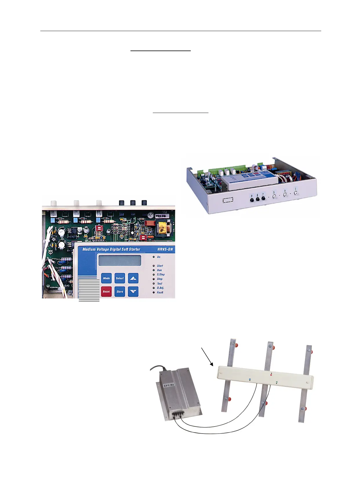
Input:
Directly connected
to H.V. bus bars
Control Module for HRVS-DN is identical for all ratings and suitable for mounting in L.V. Compartment
Control Module Connection
• Install the module in the L.V. compartment, which should be fully segregated from the H.V. compartment.
• Ensure that Control Module is properly grounded.
• Connect interposing relays to all HRVS-DN auxiliary contacts, three relays must be incorporated: Run, Fault
and By-pass.
• Fiber-optic technology is used to control the soft-starter’s firing signals. Six fiber optic leads are connected to
the firing boards on the Power Section and should be connected to the Fiber Optic connectors on the Control
Module.
• Follow the fiber optic installation directions carefully and accurately at the end of the commissioning process.
• The leads are marked with numbers from 1-6, insert each lead to its own receptacle.
Fiberoptics Connections
1. Release fiber-optic nut CCW ½ a turn.
2. Remove 25mm fiber-optic lead from the
insertion hole.
3. Identify the numbers for the F/O on the leads.
4. Insert Fiber-optic leads to their maximum
(about 18mm).
5. Tighten fiber-optic nut gently, CW direction, ½
a turn.
Fiberoptics Board
Front view of the fiber-optic board. Fiber-Optic board dip
- switches are located below f/o insertion connector # 5.
Electronic potential transformer (EPT)
Note:
Make sure the wires are connected according
the marked number
Transmitter
Receiver
Fiberoptics
Output:
3 x 120V
Input:
Power supply with