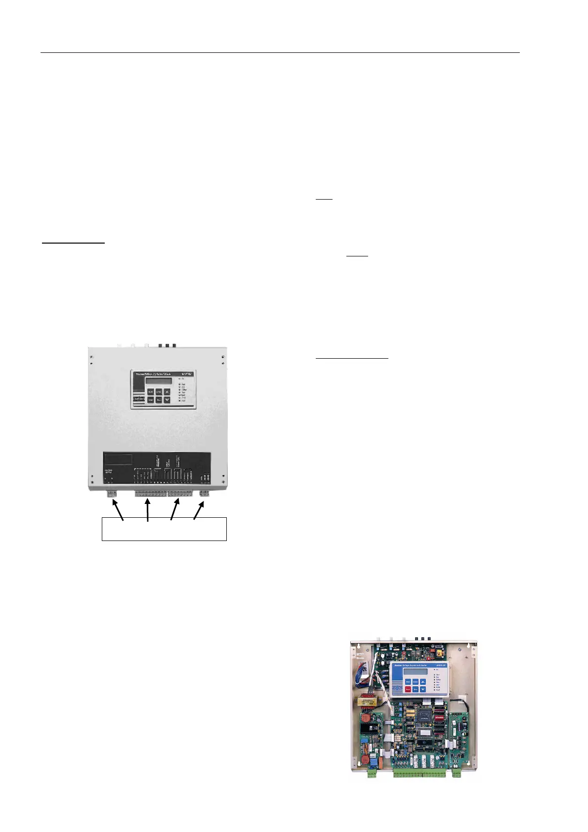
Control Terminals
8
88
8
Control Supply ......................................Terminals 1-3
110-120V or 220-240V, 50/60Hz as indicated on the
front panel is required to power the electronic circuitry.
This voltage can be supply from a grounded or
ungrounded main system. It can be supply by special
order for 110VDC.
Note: It is recommended that terminals 1-3 be
continuously connected to the Control Supply.
Firing Supply Outut .................................. Terminal 2
Output of control voltage (from terminal 1) to energize
the firing transformer. Operates during soft start and
soft stop of the soft starter.
Control Inputs
Incorporating opto - couplers to isolate the micro -
processor circuitry can be the same voltage as Control
Supply above, 110-120 or 220-240V, 50/60Hz.
By special order it can be supply for 24-110VDC.
Note: The HRVS-DN is supplied as standard with the
same voltage for Control Supply & Control
Inputs.
Stop............................................................. Terminal 4
Input from a N.C contact. To stop the motor,
disconnect control voltage from Terminal 4 for at least
250mSec.
Soft stop...................................................... Terminal 5
Input from a N.C contact. To soft stop the motor,
disconnect control voltage from Terminal 5 for at least
250mSecs.
Note: If Soft-Stop is not required, connect a jumper
between terminals 4 and 5.
Start ............................................................ Terminal 6
Input from a N.O contact. To start the motor, connect
control voltage to Terminal 6 for at least 500 mSecs.
Notes:
1. Motor will start only if Stop (4) and Soft Stop
(5) terminals are connected to control voltage.
2. Reset after a fault is not possible for as long as
Start command is present.
3. HRVS-DN ignores start within 3 sec after
stop. Wait at least 3 sec before restarting.
Test / Reset………………………….Terminal 7
Input from a N.O contact. Selection between above
functions is made from the keypad or through the
communication.
a. Test is designed to enable thyristors firing test
without mains. When connected through a
N.O. contact, closing the contact operates
Test.
b. When Reset function is selected, connect
terminal 7 momentarily to control voltage (use
a N.O momentary contact) to reset the starter.
Dual Adjust / Reset .................................... Terminal 8
Input from a N.O contact. Selection between above
functions is made from the keypad or through the
communication (see I/O Programming).
a. Dual Adjustment function is selected by
connecting terminal 8 to control voltage to
operate starter with the Dual Adjustment
characteristic.
Switching between Primary and Dual Adjustment
settings can be done before and during starting. If
a push-button arrangement is used, keep control
voltage connected at least until RUN LED is lit.
Note: When starting from a “small” Diesel Generator
or weak power supply set dip switch # 3 to on
and connect terminal 8 to control voltage to
operate starter with Generator Parameter
settings.
c. When “Reset” function is selected, connect
terminal 8 momentarily to control voltage (use
a N.O momentary contact) to reset the starter.
Common A ................................................. Terminal 9
Common for terminals 4, 5, 6, 7, 8.
Note: When control supply voltage and control input
voltages are from the same source, connect a
jumper between terminals 3 and 9.
1-3 4-9 10-21 22-24