Internal Settings
7
77
7
3. Test condition with test harness and four pairs
of dip - switches allowing a 400V motor test.
Dip Switch settings (PC2050)
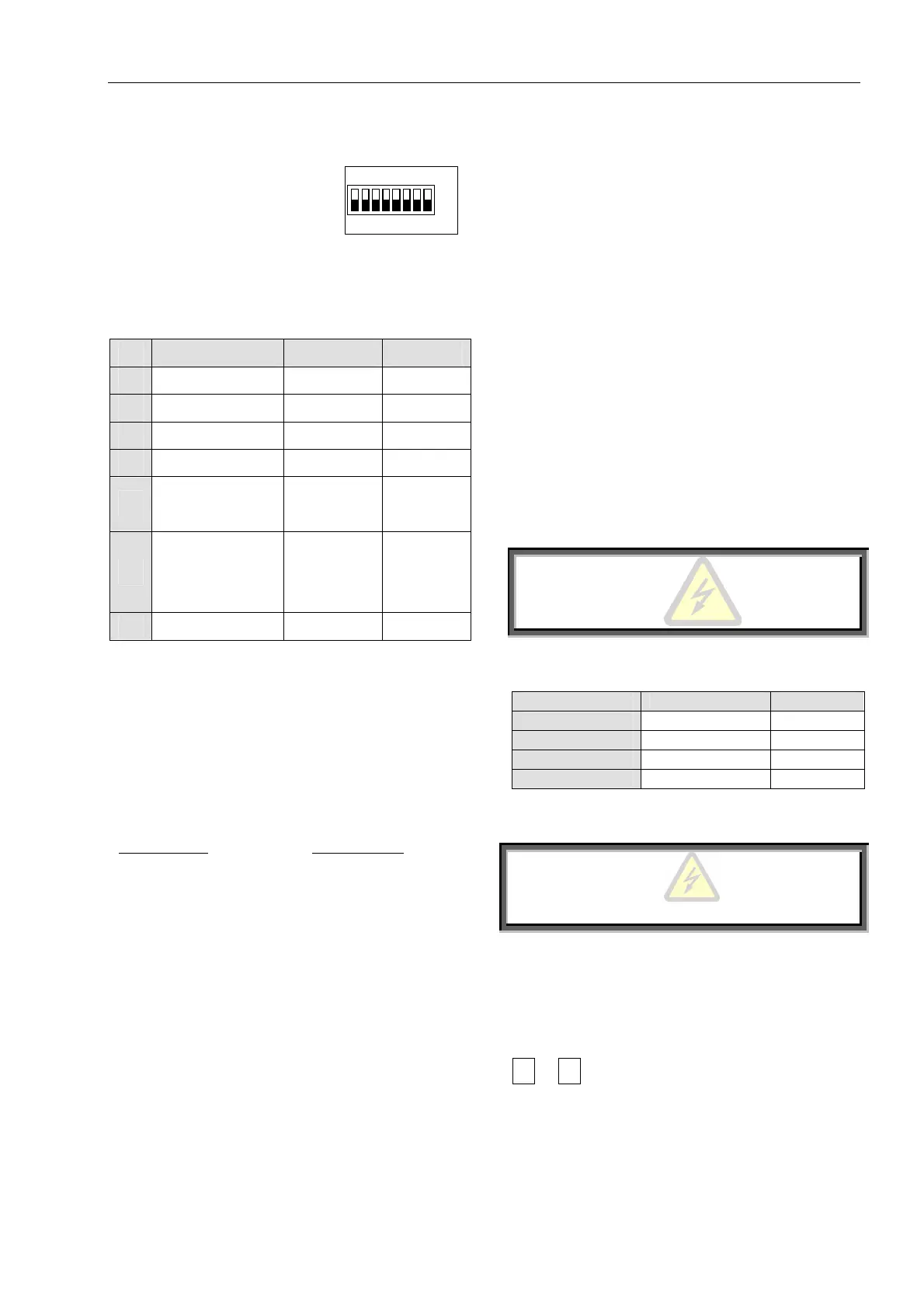
The Dip Switch module
contains eight separate switches
and located under the front
cover of the Control Module.
Dip Switch
Off
1 2 3 45 6 7 8
When necessary, carefully open the front panel and set
the switches as required.
Note: All switches are factory pre-set in OFF position.
No Switch Function Switch Off Switch On
1 Display Format Minimized Maximized
2 Tacho feedback Disabled Enabled
3 Main / Generator Main Generator
4 Must be Off
5-6
LCD-language
selection
See table
7
Special settings –
keep in Off
position
Disabled Enabled
8 Software lock Open Locked
Switch # 1 – Display Modes
For operation convenience there are two display
modes:
Maximized – Display of all possible parameters.
Minimized – Display of pre-selected parameters.
Setting Dip Switch # 1 to Off will minimize the LCD
displays.
Maximized mode
Switch 1 – On
Display only
Main parameters
Start parameters
Stop parameters
Dual adjustment
Fault parameters
I/O programming
Communication parameters
Statistical data
Minimized mode
Switch 1 – Off
Display only
Main parameters
Start parameters
Stop parameters
Statistical data
Switch # 2 – Tacho feedback (Optional)
Set Dip Switch. # 2 to On, when using Incremental
Shaft Encoder or tacho feedback.
Note: To operate tacho feedback – consult factory for
specific settings for each application.
Switch # 3 – Main / Generator control
When starting from a diesel – generator supply,
starting process can sometimes terminate due to
instability of the supply system. To operate generator
mode set Dip Switch # 3 to On and special starting
characteristics, suitable for Diesel Generator supply –
with unstable voltage & frequency become operative.
Closure of Dual Adjustment contact (terminal 8)
operates the special starting characteristics.
When operating from network voltage and alternatively
from diesel generator, set normal starting
characteristics for Main and suitable parameters for the
Diesel Generator (for example, faster acceleration,
lower current limiting, etc.) on Dual Adjustment
setting.
WARNING
When operating in Generator Mode, or with curve
“0” motor must be loaded, otherwise, vibration may
occur during starting and stopping.
Switches # 5, 6 – Language Selection
Language Switch 5 Switch 6
English Off Off
French Off On
German On Off
Spanish On On
Switch # 7 – Special settings – consult factory
WARNING
When using extended Soft-
maximum precautio
ns to avoid motor or starter
damage.
Switch # 8 – Software Lock
The software lock prevents undesired parameter
modification.
To verify that parameters are locked, press Store and
or
keys and the LCD displays, “Unauthorized
Access”.