Wiring Diagrams - Communication
15
1515
15
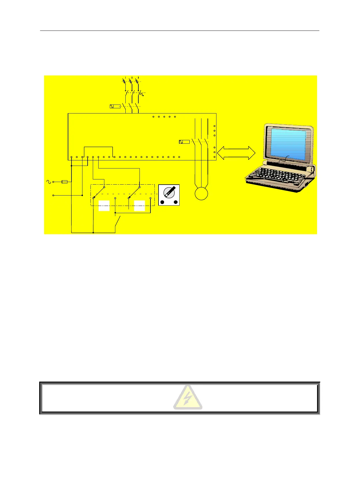
Operation via communication link with Local / Remote selector switch
• Remote: via Communication Link
• Local: Soft-start, soft-stop by maintained contact.
1 2 3 4 5 6 7 8 9 10 11 12 13 14 15 16 17 18 19 20 21
N
22
23
24
25
26
27
M
U V W
L1
L2 L3
28 29 30 31 32
Start
Soft Stop
Remote
Local
L1
b
L2
b
L3
b
RS485 to
RS232 Adapter
Twisted Shielded Pair
The communication enables remote parameter
settings and readings. For start, stop, soft-stop, dual
adjust, etc. terminals 4 and 5 must be wired as
shown.
Soft-start and soft-stop
• Program the “Serial Link Number” in the communication page according to the protocol manual.
• Disconnect control supply, so the new information will be loaded on the next time you turn it on.
• Connect a communication line (twisted shield pair) with its (+) to HRVS-DN terminal 24 and (-) to terminal
23, on MODBUS, connect the other end to your host computer containing RS-485 communication port with
MODBUS protocol. For other protocols – consult factory
• Connect other HRVS-DN terminals as follows:
1. Terminal 1, 3 and Control Supply
2. Terminal 4 to Control Supply phase
3. Terminal 9 to Common for terminals 4, 5, 6.
4. During operation via communication link, terminal 5 is connected through the “Local-Remote”
selector switch to Control Supply and start-stop commands are controlled through the communication
port.
During operation in Local mode, terminals 5 and 6 are connected to Control Supply through the start/soft-stop
toggle switch.
WARNING
Starter and host computer must be grounded when communicating with HRVS-DN