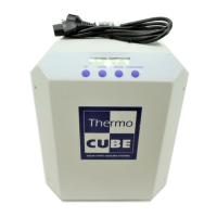
THERMOCUBE PAO CHILLER PART # 52-400-2G-1-PAO
SOLID STATE COOLING SYSTEMS, 167 MYERS CORNERS ROAD, WAPPINGERS FALLS, NY 12590 7
TELEPHONE: (845) 296-1300 FAX: (845) 296-1303 WEB: WWW.SSCOOLING.COM VERSION M9
SECTION 3
HOOK UP ________________________________________________________________
3.1 ELECTRICAL CONNECTIONS
Power: Plug line cord into 115/230 VAC, +/- 10%, 50/60 Hz,
continuous current draw is rated at 7amps (100 VAC) or 5 amps
(230VAC) at 50/60 Hz.
Fuse: 10 amp (5mm x 20mm) GDB quick acting glass, meets
IEC 127-2
Replacement Fuse: SSCS#20-22332-10, Allied Electronics
#740-9575
Alarms: The ThermoCube has two normally closed 1 amp 250V dry
contact alarm relays instead of the standard TTL alarms, one for
system faults and one for temperature exceeding the alarm range.
These contacts are wired to the 9-pin dsub connector as follows:
System Fault Alarm Common: Pin 6
System Fault Alarm: Pin 1
Temperature Alarm Common: Pin 9
Temperature Alarm: Pin 4
3.2 PLUMBING CONNECTIONS
The process fluid inlet (coolant return) and outlet (coolant supply)
connections, located on the left side, are ¼” Colder Products metal
quick disconnect fittings (female), model number LCD16004V. Note:
Viton o-rings must be specified.
3.3 AIR CONSIDERATIONS
The air inlet and outlet are located on the left and right sides
respectively. Restricting airflow into or out of the unit will impair
performance. At least 3 inches of clearance is required on each side to
ensure adequate airflow.
3.4 COOLANT FILL CAP
The coolant fill cap is located at the top rear of the unit. Twist off the
cap counter-clockwise to open. Fill reservoir prior to starting unit.
Close cap before operating.