EasyManuals Logo

Solid State Logic LIVE User Manual

Solid State Logic LIVE
45 pages
To Next Page IconTo Next Page
To Previous Page IconTo Previous Page
Page #35 background imageLoading...
Page #35 background image
SSL Live Installation Information
www.solidstatelogic.com Page 35 of 45
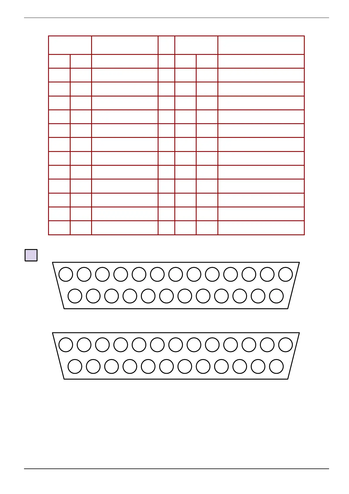
GPIO Connector Pinout
GP Output - D-type Female
Pin
Description
Pin
Description
1
Input 1A
7
+12V (450mA maximum)
14
Input 1B
20
0V Chassis
2
Input 2A
8
Output 1A
15
Input 2B
21
Output 1B
3
Input 3A
9
Output 2A
16
Input 3B
22
Output 2B
4
Input 4A
10
Output 3A
17
Input 4B
23
Output 3B
5
Input 5A
11
Output 4A
18
Input 5B
24
Output 4B
6
Input 6A
12
Output 5A
19
Input 6B
25
Output 5B
13
+12V (450mA maximum)
*19b - Console GPIO Connections
Connector Type: 25-Way D-Type Male (Inputs) and Female (Outputs)
Dimensions: Cable Dia: 55 x 15 mm (approx.) 8 mm (typical)
Screwlock thread: 440-UNC
12 opto-isolated GP input and 12 relay-closure outputs
1 2 3 4 5 6 7 8 9 10
11
12
13
14
15
16
17
18
19
20
21
22
23
24
25
Socket (Female)
13
12
11
10
9 8 7 6 5 4 3 2 1
25
24
23
22
21
20
19
18
17
16
15
14
Plug (Male)

Table of Contents

Questions and Answers:

Question and Answer IconNeed help?

Do you have a question about the Solid State Logic LIVE and is the answer not in the manual?

Solid State Logic LIVE Specifications

General IconGeneral
BrandSolid State Logic
ModelLIVE
CategoryDJ Equipment
LanguageEnglish

Related product manuals