29
User Manual
MHT-4~20K series
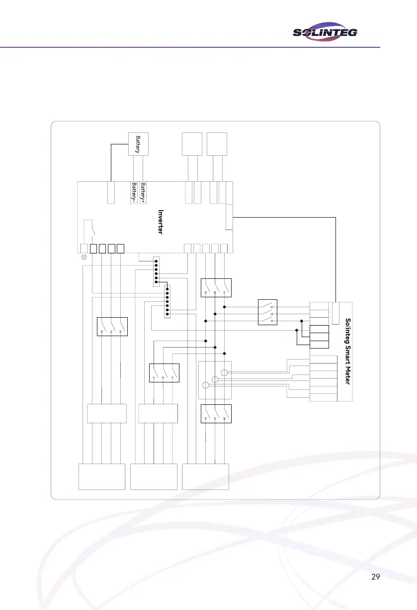
This diagram is an example for Australia and New Zealand. Neutral line of AC supply must
-
tion will not work.
Figure 5-3 Australia wiring diagram
RS485-2
Communication
PV1-
PV2-
RJ45-Meter
L1
L2
L3
N
PE
ON-GRID
L1
L2
L3
N
PV
Modules
PV
Modules
Hybrid
RJ45-BMS
Communication
The additional
grounding hole
E-BAR
N-BAR
Breaker
Breaker
Breaker
Breakerh
Solinteg CT
Main
eaker
CT-1
CT-2
CT-3
RCD
RCD
Normal
Loads
Back-up
Loads
GRID
BACK-UP
PE
*