Figure 4.14 AC Grid Terminal Connector
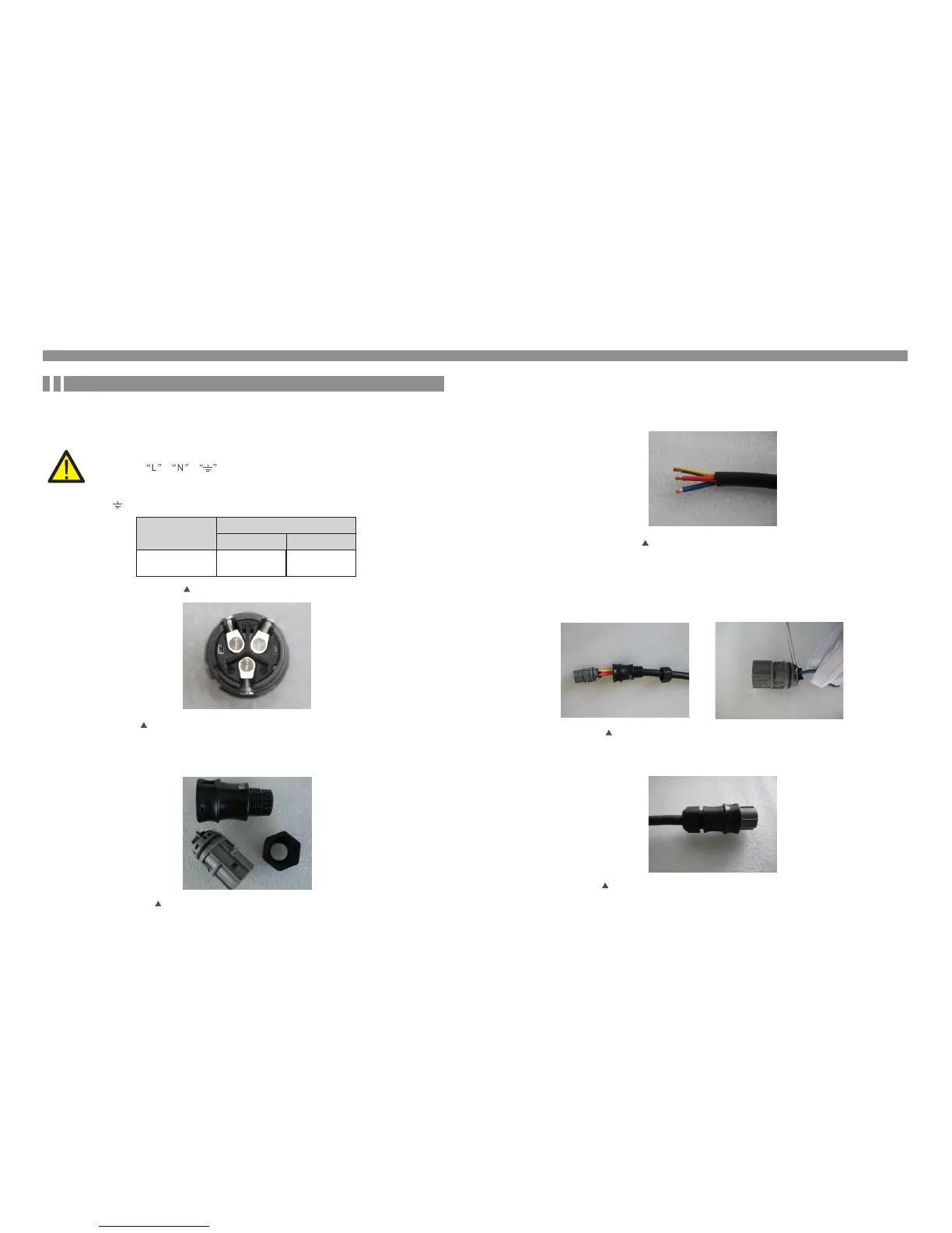
Figure 4.13 AC Grid Terminal Connector Inside
The steps to assemble the AC grid terminal connectors are listed as follows:
a) Disassemble the AC connector. Strip the AC wires about 6mm,
Figure 4.15 Stripped AC Wires
4. Installation
Each Solis Mini Single Phase Inverter is supplied with an AC grid terminal connector.
There are symbols marked inside the connector ( see Figure
4.11), the Line wire of grid must be connected to“L”terminal; the Neutral wire
of grid must be connected to“N”terminal; the Earth of grid must be connected
to“ ”(see Figure 4.11).
For all AC connections, 2.5- 6mm 105 ℃ cable is required to be used. Please make sure
2
the resistance of cable is lower than 1 ohm. If the wire is longer than 20m, it's recommended
to use 6mm cable.
2
WARNING:
4. Installation
Cable type
2.5~6.0mm²
Cross section
Range
Industry generic
grid cable
Recommended
value
6mm²
Table 4.2 Grid cable size
4.3.2 Connect grid side of inverter
.17..16.
c) Tighten up the cap on the terminal (as shown in Figure 4.15).
Figure 4.17 Tighten up the Cap on the Terminal
b) Fix the green and yellow wire to the ground terminal. Fix the red(or brown) wire to L
(line) terminal. Fix the blue wire to N(Neutral). Tight the screws on the connector. Please
try to pull out the wire to make sure the it’s well connected.
Figure 4.16 Connect Wires to the Terminal