4. Installation
d) Connect the AC grid terminal connector to the inverter. Small click will confirm
connection.
Figure 4.18 Connect the AC Connector to the Inverter
4. Installation
Note: Connection for Split phase grid.
When connect to 208/220/240Vsplit phase, please connect L1 to “L” terminal,
L2 to “N” terminal. Also connect earth to ground terminal.
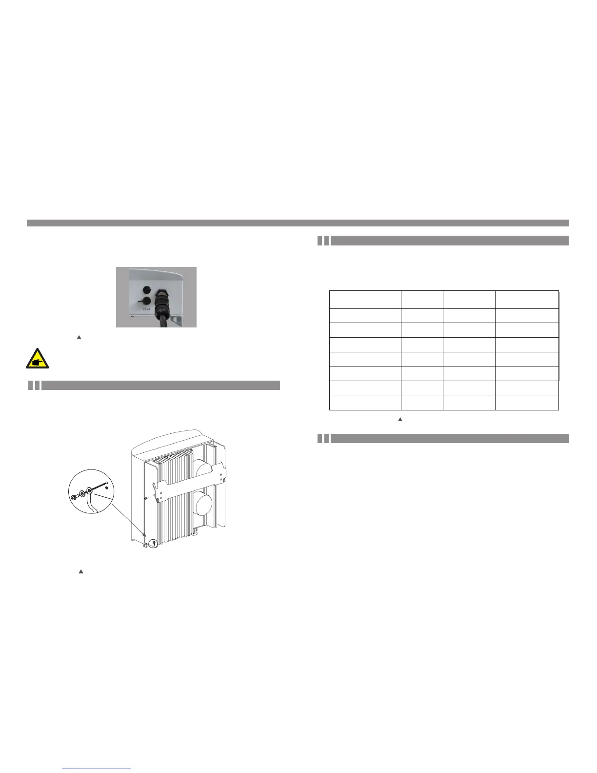
4.3.3 External ground connection
An external ground connection is provided at the right side of inverter.
Prepare OT terminals: M4. Use proper tooling to crimp the lug to the terminal.
Connect the OT terminal with ground cable to the right side of inverter. The torque is
20 in-lbs (2Nm).
Figure4.19 Connect the external grounding conductor
.19..18.
The inverter can be monitored via Wi-Fi or GPRS. All Ginlong Solis communication
devices are optional (Figure 4.9). For connection instructions, please refer to the Ginlong
Solis Monitoring Device installation manuals.
To protect the inverter's AC grid connection conductors, Ginlong Solis recommends installing
breakers that will protect against overcurrent. The following table defines OCPD ratings for
the Ginlong Solis 6-10kW single phase inverters.
Inverter
Solis-mini-700-4G
Rated
voltage(V)
230V/240V
Rated output
power (kW)
Current for protection
device (A)
0.7
1
1.5
2
3
3.6
10
2.5
Solis-mini-3600-4G
Solis-mini-3000-4G
Solis-mini-2500-4G
Solis-mini-2000-4G
Solis-mini-1500-4G
Solis-mini-1000-4G
20
20
15
15
10
10
4.3.4 Max. over current protection device (O CPD)
Table 4.3 Rating of grid OCPD
230V/240V
230V/240V
230V/240V
230V/240V
230V/240V
230V/240V
4.3.5 Inverter monitoring connection