67EV1
12
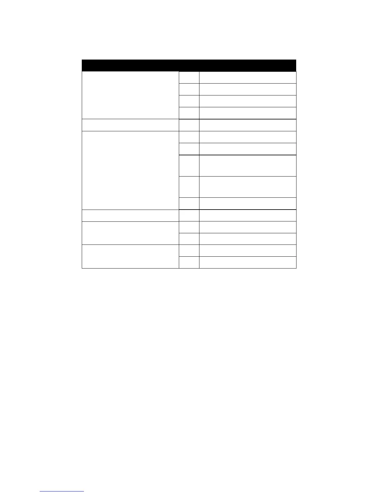
2-4.1 J2 SWITCH SIGNAL SUMMARY
HDD INDICATOR LED (PIN1 ~ PIN4)
• This connector connects with the hard disk indicator LED on the case.
INFRARED PORT MODULE CONNECTOR (PIN6 ~ PIN10)
• The system board provides a 5-pin infrared connector for an optional wire-
less transmitting and receiving module. Pin 6 through pin 10 are Transmit,
GND, Receive (low speed), Receive (high speed) and Vcc, respectively.
POWER SWITCH (PIN12 ~ PIN13)
• Toggle pin 12 and pin 13 for turning ON/OFF of the power supply. (For ATX
power only)
SLEEP SWITCH (PIN14 ~ PIN15)
• Toggle this jumper forces the system to sleep and the system won’t wake
up until the hardware event is coming. (The BIOS Power Management
setting must be ENABLED)
N.C. Empty11
Power Switch
GND12
Power Switch for ATX13
Sleep Switch
GND14
Sleep Signal15
Infrared Connector
6
7
8
Infrared Transmit Signal
GND
Infrared Receive Signal¤
(Low Speed)
9
Infrared Receive Signal¤
(High Speed)
10 +5V
N.C. 5 Empty
HDD LED Connector
1
2
3
4
J2 Pin Signal Description
+5V
HDD LED Signal
HDD LED Signal
+5V