67EV1
13
N.C. Empty13
Keylock Connector
Keylock Signal11
GND12
Reset Switch
Reset Signal5
GND6
Power LED Connector
+5V8
Empty9
GND10
Power Saving Connector
Empty14
Empty15
N.C. 7 Empty
Speaker
1
2
3
4
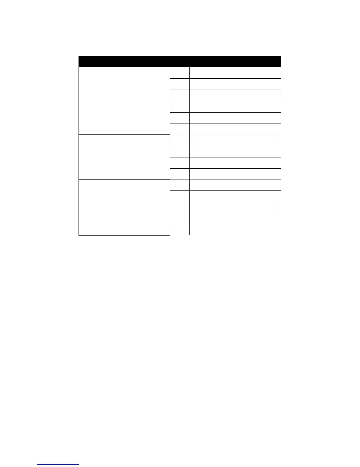
J3 Pin Signal Description
Speaker Signal
Empty
GND
+5V
2-4.2 J3 SWITCH SIGNAL SUMMARY
SPEAKER CONNECTOR (PIN1 ~ PIN4)
• The speaker is a 4-pin connector to connect with the system and the speaker.
RESET SWITCH (PIN5 ~ PIN6)
• The system board has a 2-pin connector for rebooting your computer with-
out having to turn off the power switch. This prolongs the life of the system’s
power supply.
POWER LED and KEYLOCK SWITCH (PIN8 ~ PIN12)
• The keylock switch is a 5-pin connector for locking the keyboard for secu-
rity purposes. Pin 8 ~ pin 10 is connected to power LED and pin 11 ~ pin 12
is connected to keylock switch.
GREEN LED (PIN14 ~ PIN15)
• Reserved.