Solwise Ltd., www.solwise.co.uk, sales@solwise.co.uk
- 7 -
external sensor triggered, IP Camera can be programmed to send an email with
picture or control the internal relay output.
Input pins can connect 2 sensors. The sensor should provide open/close signal only. The
two lines of sensor 1 should connect to Pin 3 & Pin 4; the two lines of sensor 2 should
connect to Pin 5 & Pin 4.
Output Pins: IP Camera has an internal relay. Relay’s two normally open contacts are
represented by Pin 1 and Pin 2. You may use it to control one external load below AC/DC
36V & 2 Amp.
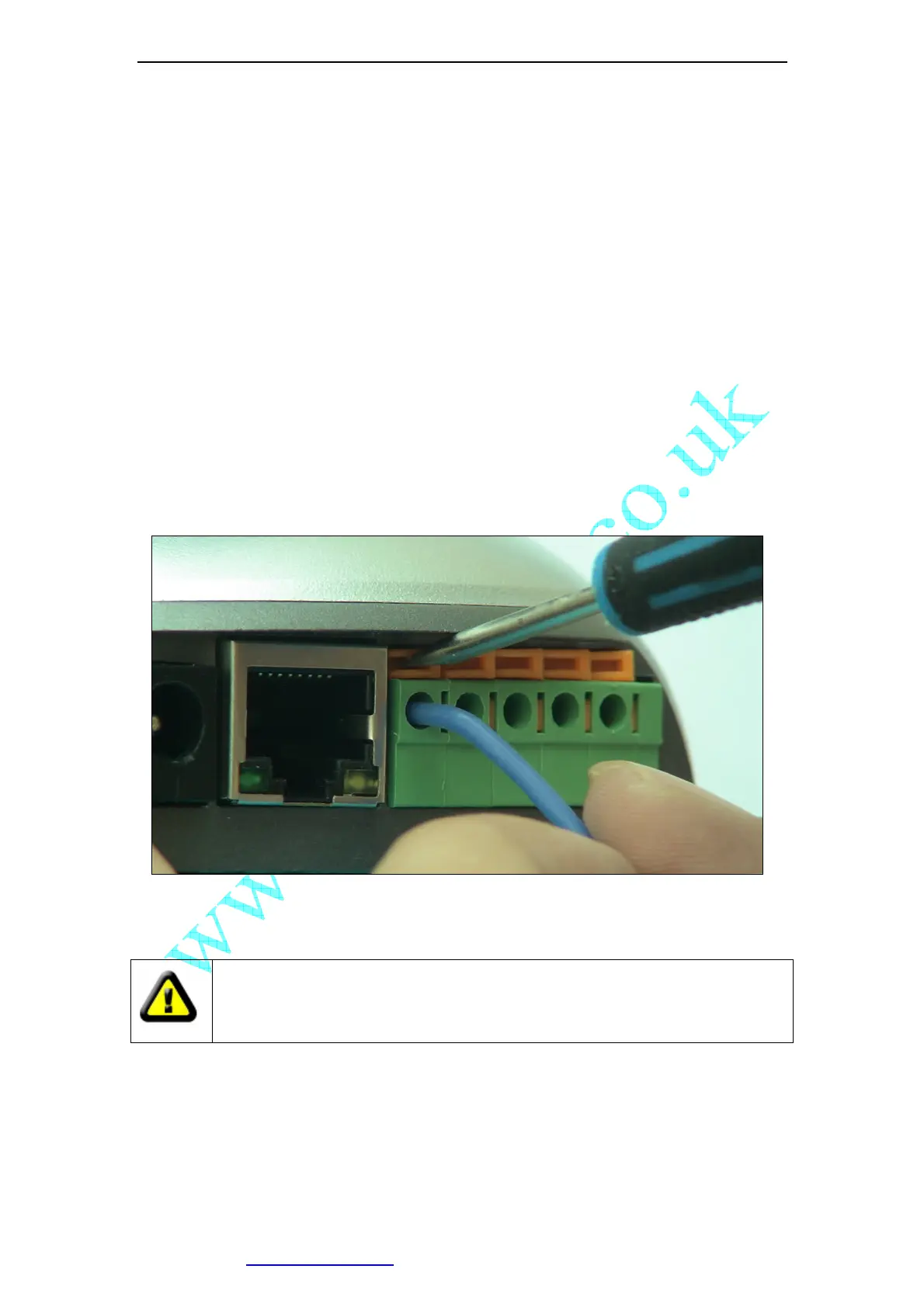
While connecting input and output pins, strip off the protect rubber of wire for 5mm, the
use a small screwdriver to depress and latch down the orange tabs over holes, Insert the
red wire into hole until the insulation just reaches the back of the camera, use the
screwdriver to press down and release the orange tab above hole locking the wire in
place. Repeat the steps for other wires.
Figure 9 Input & Output Pins Connection
External Power Socket:Connect to a 5V AC-DC adapter.
CAUTION: Make sure to only use the power adapter supplied with your IP
Camera. Using a non-approved power adapter may damage the camera.
RJ-45 Ethernet Socket: Connects your IP Camera to LAN.
CF Card Socket: Insert a Compact Flash Card for scheduler or sensor trigger’s images
storage. Support volume is 1MByte to 2GByte. CF Card should be format as
FAT16/FAT32 before inserted.